Train power supply load test device

A technology of power supply load and test device, applied in the field of train power supply load test device, can solve the problem of lack of compatible load test equipment and the like

Pending Publication Date: 2020-05-12
BEIJING RAILWAY INST OF MECHANICAL & ELECTRICAL ENG
View PDF0 Cites 0 Cited by
  • Summary
  • Abstract
  • Description
  • Claims
  • Application Information

AI Technical Summary

Problems solved by technology

[0003] However, at present, many locomotive depots responsible for passenger transport tasks do not have load

Method used


Image

  • Train power supply load test device
  • Train power supply load test device
  • Train power supply load test device

Examples


Embodiment 1

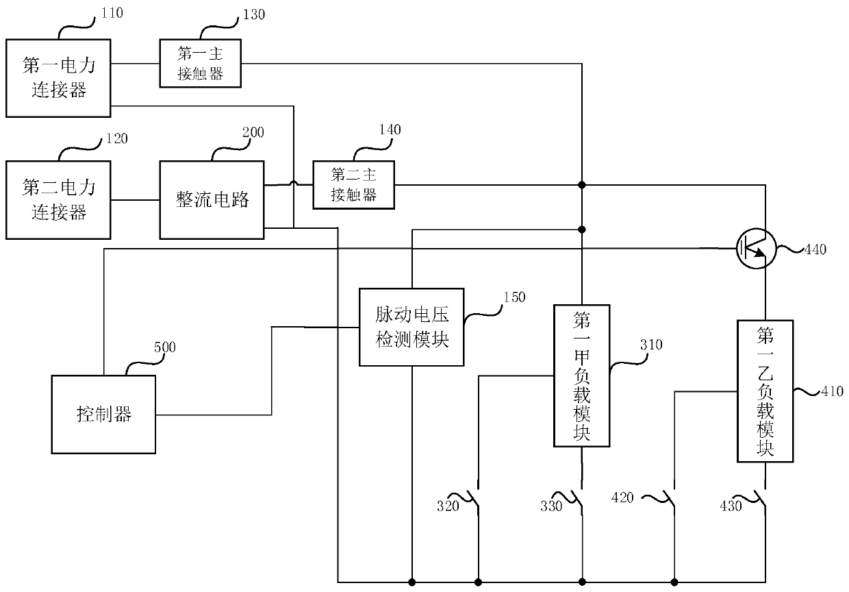
[0017] figure 1 It is a structural block diagram of a train power supply load test device provided in Embodiment 1 of the present invention. Exemplary, refer to figure 1 , the train power supply load test device includes: a first power connector 110, a second power connector 120, a first main contactor 130, a second main contactor 140, a rectifier circuit 200, a switch module 440, at least two first load module (exemplary reference figure 1 , shows two first load modules, wherein the first first A load module 310, the second first B load module 410), the first A switch 320 corresponding to the first A load module 310 and the second A switch 330, the first B switch 420 and the second B switch 430 corresponding to the first B load module 410, the pulsating voltage detection module 150 and the controller 500;

[0018] Wherein, the first power connector 110 is used to connect a DC power supply, the first output end of the first power connector 110 is connected to the first load...

Embodiment 2

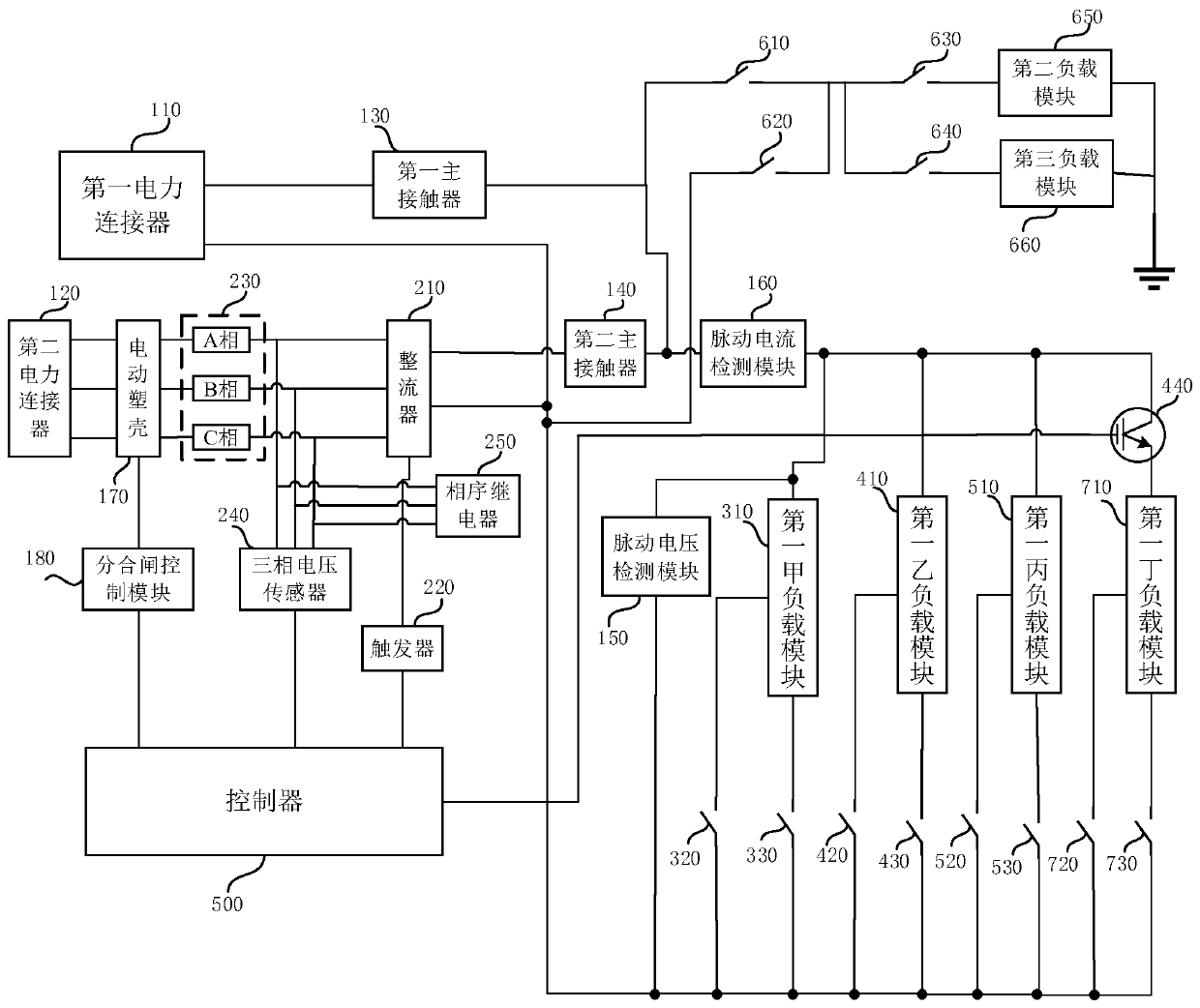
[0024] figure 2It is a structural block diagram of a train power supply load test device provided in Embodiment 2 of the present invention. On the basis of the above technical solutions, for example, refer to figure 2 , the train power supply load test device also includes a second load module 650, a third load module 660, a third switch 610, a fourth switch 620, a fifth switch 630 and a sixth switch 640, the first end of the third switch 610 is connected to the The first load connection line is connected, the first end of the fourth switch 620 is connected to the second load connection line, the second end of the third switch 610 is electrically connected to the second end of the fourth switch 620, the first end of the fifth switch 630 end is electrically connected to the second end of the third switch 610, the second end of the fifth switch 630 is electrically connected to the first end of the second load module 650, the second end of the second load module 650 is grounde...


PUM


Abstract

The embodiment of the invention discloses a train power supply load test device. The device comprises a first power connector, a second power connector, a first main contactor, a second main contactor, a rectifying circuit, a switch module, at least two first load modules, a first switch, a second switch, a pulsating voltage detection module and a controller, wherein the first switch and the second switch correspond to the first load modules. Whether a direct-current power supply and an alternating-current power supply are connected to a first load or not is determined by controlling the firstmain contactor, the second main contactor, the first switch and the second switch to be switched on or off through the controller to realize load detection testing. Therefore, a problem that no passenger locomotive train power supply system load test equipment compatible with two power supply systems exists in an existing locomotive depot is solved, and the effect that the load test requirementsof trains compatible with two power supply systems of an internal combustion locomotive and an electric locomotive can be met is achieved.

Description

technical field [0001] Embodiments of the present invention relate to the technical field of locomotive power supply, in particular to a load test device for train power supply. Background technique [0002] Electric locomotives and diesel locomotives mainly engaged in passenger transport are equipped with train power supply devices to meet the electricity needs of air conditioning, heating, lighting, furnaces and other electrical appliances in passenger cars. The quality of the power supply system of passenger locomotives is closely related to the travel life of passengers. Therefore, after the major, medium and minor repairs of passenger locomotives, the train power supply system must be tested and inspected, and even the train power supply system of the back-haul locomotives should be tested and inspected before they leave the warehouse and go online, especially the train power supply of passenger locomotives. System load test. [0003] However, at present, many locomoti...

Claims


Application Information

Patent Timeline
IPC IPC(8): G01R31/00G01R1/04
CPCG01R1/0416G01R31/005
Inventor 黎莎喻贵忠
Owner BEIJING RAILWAY INST OF MECHANICAL & ELECTRICAL ENG
Why Eureka
Try Eureka