Optical lens and assembly method thereof

A technology for optical lenses and assembly parts, applied in the field of optical lenses, can solve problems such as the inability to meet the 200-degree expansion of plastic lenses, the radial deformation, the misalignment of the lens and the lens barrel, and the impact on the optical performance of the lens, etc., to achieve high positioning accuracy , reduce the impact, reduce the effect of force

Active Publication Date: 2022-03-29
NINGBO SUNNY AUTOMOTIVE OPTECH
View PDF8 Cites 0 Cited by
  • Summary
  • Abstract
  • Description
  • Claims
  • Application Information

AI Technical Summary

Problems solved by technology

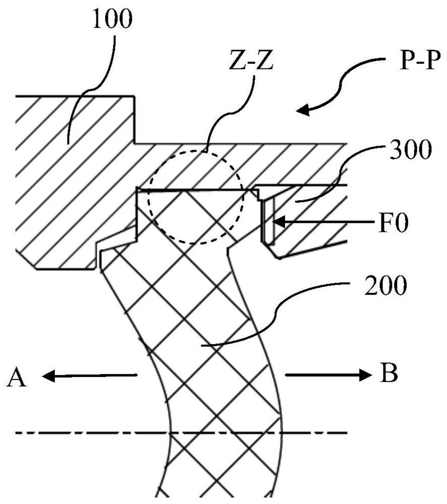
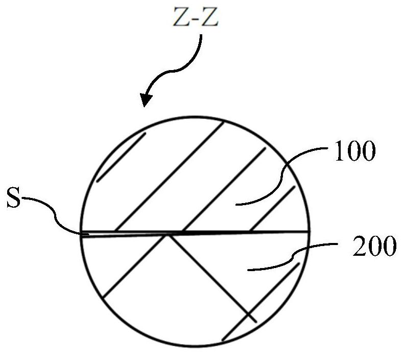
At this time, because the matching gap S between the plastic lens 200 and the lens barrel 100 is too small (such as image 3 As shown), the radial expansion of the plastic lens 200 and the radial deformation transformed by the axial expansion cannot be satisfied, so that the radial deformation is also limited by the lens barrel 100, so that the expansion of the plastic lens 200 is not restricted. A surface change occurs at the optically active region of the , specifically, such as figure 2 As shown in , the front surface of the optically effective area of ​​the plastic lens is mainly deformed along the direction indicated by the arrow A, while the rear surface is mainly deformed along the direction indicated by the arrow B, resulting in the surface shape of the plastic lens which can directly affect the lens optics. non-negligible change in performance
[0005] In order to reduce the axial deformation of the plastic lens, it is necessary to increase the fitting gap between the lens and the lens barrel so that the radial expansion / deformation is not limited by the lens barrel. Misalignment between lens barrels (i.e. decentering)

Method used


Image

  • Optical lens and assembly method thereof
  • Optical lens and assembly method thereof
  • Optical lens and assembly method thereof

Examples


Embodiment Construction

[0041] For a better understanding of the application, various aspects of the application will be described in more detail with reference to the accompanying drawings. It should be understood that these detailed descriptions are descriptions of exemplary embodiments of the application only, and are not intended to limit the scope of the application in any way. Throughout the specification, the same reference numerals refer to the same elements. The expression "and / or" includes any and all combinations of one or more of the associated listed items.

[0042] It should be noted that in this specification, expressions of first, second, etc. are only used to distinguish one feature from another, and do not represent any limitation on the features. Accordingly, a first body discussed hereinafter may also be referred to as a second body without departing from the teachings of the present application.

[0043] In the drawings, the thickness, size and shape of objects have been slight...


PUM


Abstract

The application provides an optical lens, comprising a lens barrel, a first lens, a front fixing element and a rear fixing element, the first lens has an opposite front surface and a rear surface, and an outer diameter surface connecting the front surface and the rear surface The front fixing element and the rear fixing element are respectively in contact with a part of the front end surface and a part of the rear end surface to fix the first lens; wherein, there may be a fit gap between the outer diameter surface and the inner wall of the lens barrel; a part of the front end surface, the rear end surface A portion of the end surface, and at least two of the surfaces of the front and rear fixation elements that contact the front end surface and the rear end surface, respectively, are tapered. The present application also provides an assembly method of an optical lens, including processing the lens, the lens barrel, the front fixing element and the rear fixing element, so that the lens is in contact with at least one of the front and rear fixing elements in a tapered bearing manner, and There is a matching gap with the inner wall of the lens barrel; the front and rear fixing elements and lenses are installed in the lens barrel.

Description

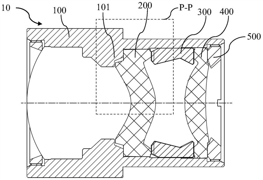
technical field [0001] The present application relates to the field of optical lenses, and more specifically relates to an optical lens and an assembly method thereof that reduce the change of lens surface shape under high temperature. Background technique [0002] The plastic lens in the optical lens is easy to expand and deform under high temperature conditions, which may lead to indeterminate changes in the surface shape of the plastic lens, thereby affecting the final imaging quality. [0003] Axial deformation is an important factor affecting the shape of the lens. First refer to Figure 1 to Figure 3 Analyze the causes of axial deformation in the prior art. As shown in the figure, the front end surface of the plastic lens 200 of the optical lens 10 abuts against the inner boss 101 of the lens barrel 100 in the axial direction by means of a platform surface, and usually by means of a rear fixing element (in this example) Among them, including the first spacer 300, the...

Claims


Application Information

Patent Timeline
Patent Type & Authority Patents(China)
IPC IPC(8): G02B7/02G02B7/00
CPCG02B7/02G02B7/00
Inventor 陈城俞洪涛邢圆圆徐超
Owner NINGBO SUNNY AUTOMOTIVE OPTECH
Why Eureka
Try Eureka