Optical lens polishing device and polishing process

A technology for optical lenses and polishing devices, which is applied to grinding/polishing safety devices, optics, optical components, etc., can solve the problems of reducing the surface shape change of optical lenses, and achieves the improvement of polishing effect, reducing surface shape change, and weakening beating. Effect

Active Publication Date: 2021-06-29
DONGGUAN FURAO PHOTOELECTRIC CO LTD
View PDF25 Cites 2 Cited by
  • Summary
  • Abstract
  • Description
  • Claims
  • Application Information

AI Technical Summary

Problems solved by technology

[0006] In view of the problems existing in the prior art, the object of the present invention is to provide an optical lens polishing device and a polishing process, which exerts pressure on the optical lens through the action of magnetic force to ensure equal pressure on each part of the mirror surface, effectively avoiding optical The problem of uneven force on the lens, and to reduce the beating of the lens to a certain extent, so as to improve the polishing effect. During the polishing process, the thermal expansion ball expands through the transfer of frictional heat, so as to push the color developing parts out without changing the color. The color marked ball indicates that no friction is sent here, which indirectly indicates that the lens is under uneven force at this time. In this way, through the change of color, the staff can understand the polishing situation more easily and intuitively and make adjustments in time, thereby Effectively reduce the surface shape changes of optical lenses

Method used


Image

  • Optical lens polishing device and polishing process
  • Optical lens polishing device and polishing process
  • Optical lens polishing device and polishing process

Examples


Embodiment

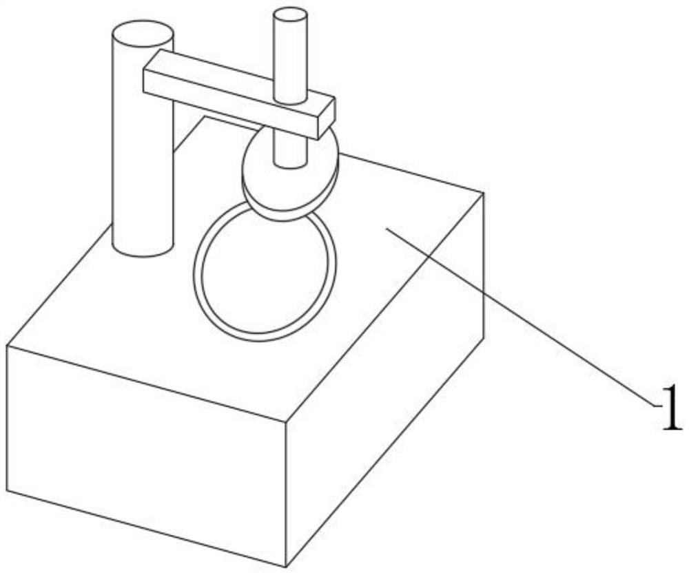
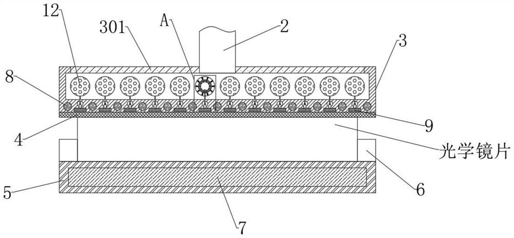
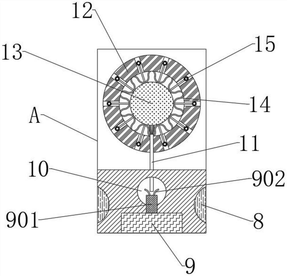
[0044] see Figure 1-6 , an optical lens polishing device and a polishing process, including a polishing machine body 1, please refer to figure 1 The polishing machine body 1 includes a telescopic column 2, a polishing disc 3 is installed at the lower end of the telescopic column 2, and an observation window 301 is fixedly inlaid on the side wall of the upper end of the polishing disc 3, and the observation window 301 is made of a transparent material, which is to facilitate the work. The personnel sees the color change of the color marking ball 12, and the lower end of the polishing disc 3 is bonded with a polishing skin 4, the polishing machine body 1 includes a rotating base 5, and two symmetrically arranged pneumatic clamps 6 are installed on the upper end of the rotating base 5, and An optical lens is clamped between two pneumatic clamps 6, and an electromagnet 7 is installed in the middle of the rotating base 5 (its specific model can be selected according to actual need...


PUM


Abstract

The invention discloses an optical lens polishing device and a polishing process, and belongs to the field of optical lens processing. The optical lens polishing device applies pressure to an optical lens through the action of magnetic adsorption, ensures that the pressure at each position of the lens surface is equal, effectively avoids the problem of uneven stress of the optical lens, and weakens the bounce of the lens to a certain extent, thereby improving the polishing effect. In the polishing process, a thermal expansion ball is expanded through the transmission of friction heat, so that a color developing piece is pushed out, and a color marking ball which does not change color indicates that no friction is sent here, thereby indirectly indicating that the lens has the condition of uneven stress at the moment. In the abovementioned way, the color change enables the staff to know the polishing condition more easily and more intuitively and make adjustment in time, thereby effectively reducing the surface type change of the optical lens.

Description

technical field [0001] The invention relates to the field of optical lens processing, and more specifically relates to an optical lens polishing device and a polishing process. Background technique [0002] Optical lenses are lenses made of optical glass. The definition of optical glass is glass that has specific requirements for optical properties such as refractive index, dispersion, transmittance, spectral transmittance, and light absorption, and has uniform optical properties. Glass that can change the direction of light propagation and change the relative spectral distribution of ultraviolet, visible or infrared light. Optical glass in the narrow sense refers to colorless optical glass; optical glass in the broad sense also includes colored optical glass, laser glass, quartz optical glass, anti-radiation glass, ultraviolet and infrared optical glass, fiber optic glass, acousto-optic glass, magneto-optical glass and photochromic Glass. Optical glass can be used to manu...

Claims


Application Information

Patent Timeline
Patent Type & Authority Applications(China)
IPC IPC(8): B24B13/00B24B13/005B24B55/00B24B57/02
CPCB24B13/00B24B13/0055B24B55/00B24B57/02
Inventor 罗俊涛
Owner DONGGUAN FURAO PHOTOELECTRIC CO LTD
Why Eureka
Try Eureka