
Optical anti-shake method and device of camera equipment

A camera equipment, optical anti-shake technology, applied in the direction of image communication, color TV parts, TV system parts, etc., to achieve the effect of ensuring the anti-shake performance

Active Publication Date: 2020-05-12
ZHEJIANG DAHUA TECH CO LTD
View PDF6 Cites 2 Cited by
  • Summary
  • Abstract
  • Description
  • Claims
  • Application Information

AI Technical Summary

Problems solved by technology

[0005] Embodiments of the present invention provide an optical anti-shake method and device for camera equipment, to at least solve the problem of ensuring the transient and Steady State Response Problem

Method used

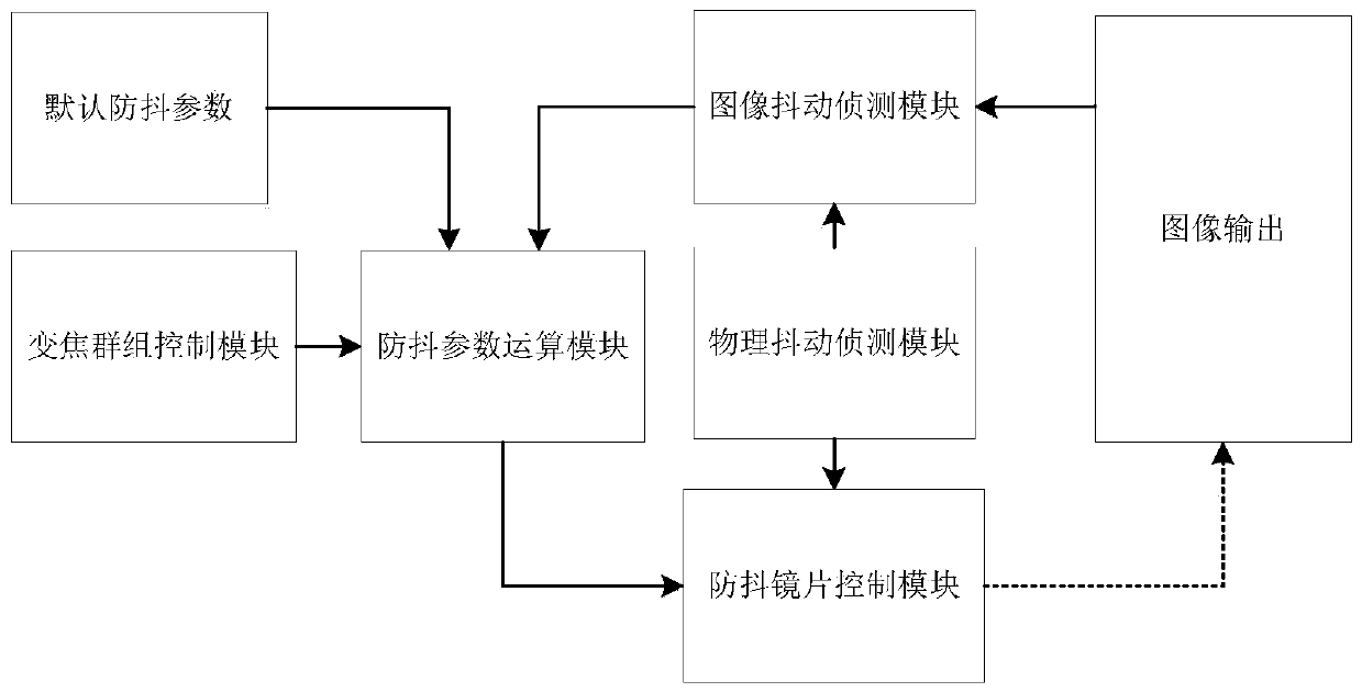
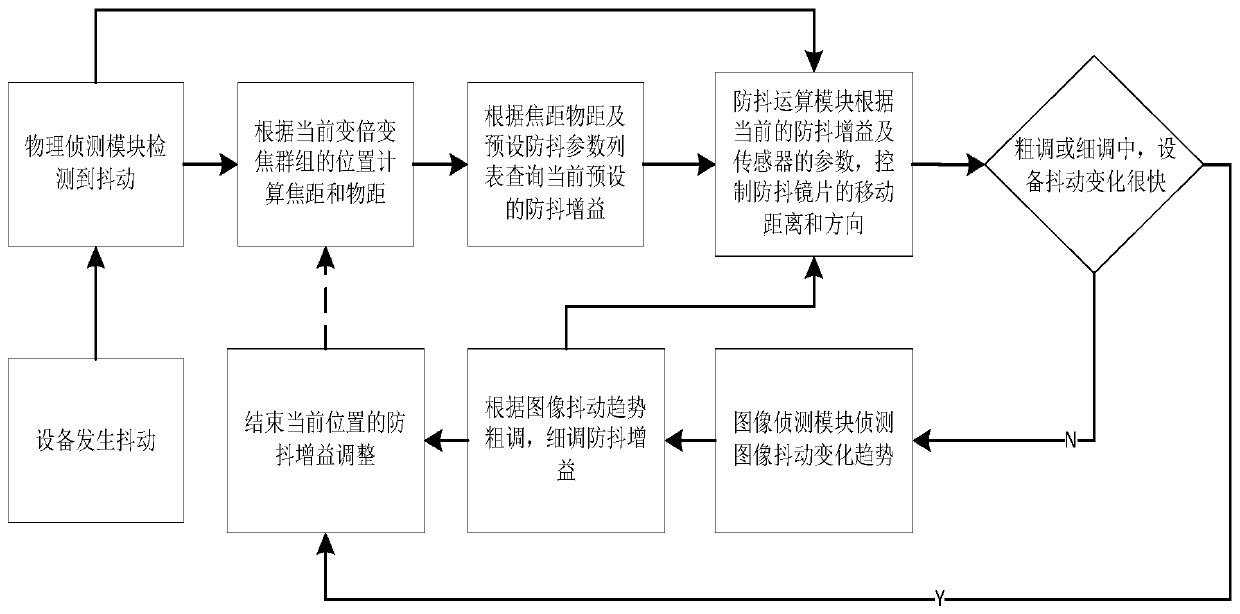

Image

  • Optical anti-shake method and device of camera equipment
  • Optical anti-shake method and device of camera equipment
  • Optical anti-shake method and device of camera equipment

Examples


Embodiment Construction

[0033] Hereinafter, the present invention will be described in detail with reference to the drawings and examples. It should be noted that, in the case of no conflict, the embodiments in the present application and the features in the embodiments can be combined with each other.

[0034] It should be noted that the terms "first" and "second" in the description and claims of the present invention and the above drawings are used to distinguish similar objects, but not necessarily used to describe a specific sequence or sequence.

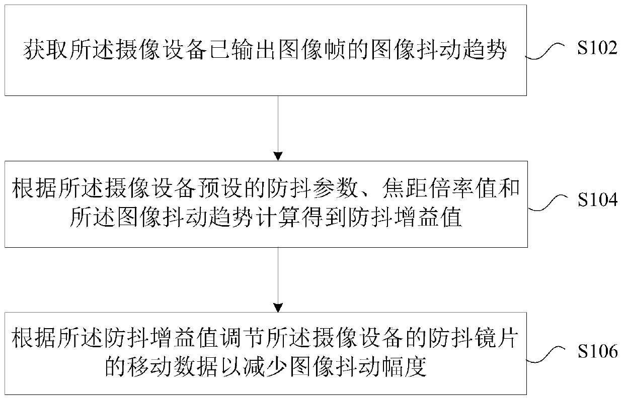
[0035] In this embodiment, an optical anti-shake method running on an imaging device is provided, figure 1 is a flow chart of a method according to an embodiment of the present invention, such as figure 1 As shown, the process includes the following steps:

[0036] Step S102, acquiring the image shake trend of the output image frames of the camera device;

[0037] Step S104, calculating an anti-shake gain value according to the anti-shake parameters...


PUM


Abstract

The invention provides an optical anti-shake method and an optical anti-shake device for camera equipment. The method comprises the following steps: acquiring an image shake trend of an image frame output by the camera equipment; carrying out calculation to obtain an anti-shake gain value according to an anti-shake parameter preset by the camera equipment, a focal length multiplying power value and the image shake trend; and adjusting movement data of an anti-shake lens of the camera equipment according to the anti-shake gain value so as to reduce the image shake amplitude. According to the invention, the shaking degree of the output image is fed back to the optical anti-shake system, and movement data of the anti-shake lens is automatically adjusted in combination with the feedback information, so that the shake amplitude of the image is minimized, the closed-loop control of the image and the optical anti-shake system is realized, and transient and steady anti-shake performance of theanti-shake equipment is ensured.

Description

technical field [0001] The invention relates to the field of optical anti-shake, in particular to an optical anti-shake method and device for an imaging device. Background technique [0002] During the shooting process of the surveillance camera, it may be shaken due to the influence of its environment, and at this time, the image captured by the surveillance camera will become blurred. In order to ensure that the image is clear during camera shooting, it is necessary to introduce camera anti-shake related technologies. [0003] At present, the commonly used anti-shake technology is optical anti-shake: the small movement of the camera is detected by the gyroscope inside the lens, and the signal is sent to the microprocessor to immediately calculate the amount of displacement that needs to be compensated, and then through the compensation lens group, according to The shake direction and displacement of the lens are compensated, so as to effectively overcome the image blur ca...

Claims


Application Information

Patent Timeline
Patent Type & Authority Applications(China)
IPC IPC(8): H04N5/232
CPCH04N23/6811H04N23/685
Inventor 刘峰明孙徐飞
Owner ZHEJIANG DAHUA TECH CO LTD
Learn More