Bundling pipe pay-off rack for optical communication cables

A technology for communication optical cables and pay-off racks, which is used in the transportation of filamentous materials, thin material handling, transportation and packaging, etc., can solve the problems of unstable product quality, high resource cost consumption, and cumbersome manual operation, and achieve more than protection. Long-term stability, reducing labor consumption, and simple equipment structure

Pending Publication Date: 2020-02-28
TONGDING INTERCONNECTION INFORMATION CO LTD
View PDF0 Cites 2 Cited by
  • Summary
  • Abstract
  • Description
  • Claims
  • Application Information

AI Technical Summary

Problems solved by technology

[0003] The purpose of the present invention is to address the deficiencies of the prior art, to provide a bundle tube pay-off rack for communication optical cables, to solve the problems of obsolete equipment, low production rate, unstable product quality, high resource cost consumption, cumbersome manual operations and safety issues. high risk issues

Method used


Image

  • Bundling pipe pay-off rack for optical communication cables
  • Bundling pipe pay-off rack for optical communication cables
  • Bundling pipe pay-off rack for optical communication cables

Examples


Embodiment Construction

[0023] In order to make the purpose, technical solutions and advantages of the embodiments of the present invention clearer, the technical solutions in the embodiments of the present invention will be clearly and completely described below in conjunction with the drawings in the embodiments of the present invention. Obviously, the described embodiments It is a part of embodiments of the present invention, but not all embodiments. Based on the embodiments of the present invention, all other embodiments obtained by persons of ordinary skill in the art without making creative efforts belong to the protection scope of the present invention.

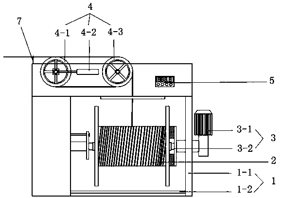
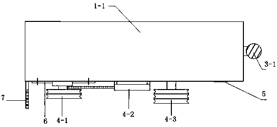
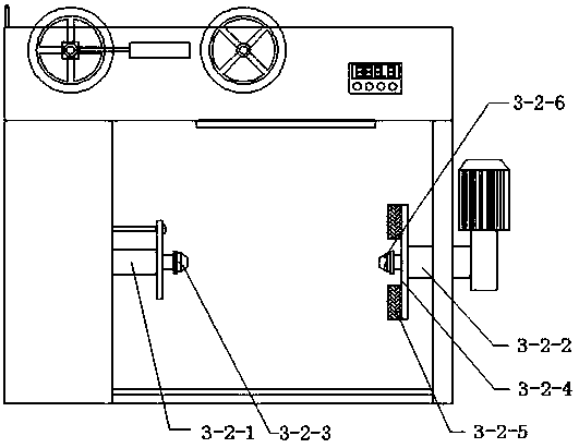
[0024] refer to Figure 1-2 , a beam tube pay-off rack for communication optical cables, comprising a pay-off rack 1, a beam tube tray 2, a chuck drive device 3 and a pay-off tension wheel 4, and the pay-off rack 1 includes a pay-off rack main body 1-1 , the beam tube tray tool 2 is horizontally installed inside the pay-off frame main body 1...


PUM


Abstract

The invention provides a bundling pipe pay-off rack for optical communication cables. The bundling pipe pay-off rack for the optical communication cables comprises a pay-off rack, a bundling pipe disc, a chuck drive device and a pay-off tension wheel, wherein the bundling pipe disc is horizontally installed in a pay-off rack main body; an output shaft of the chuck drive device is fixedly connectedwith a rotary shaft of the bundling pipe disc; the pay-off tension wheel comprises a V-shaped-groove movable pulley, a V-shaped-groove fixed pulley and a telescopic cylinder, and the telescopic cylinder is capable of driving the V-shaped-groove movable pulley to horizontally slide in a certain range; a drive motor is capable of driving the bundling pipe disc to rotate to take up and pay off a bundling pipe, the bundling pipe is led out from the bundling pipe disc, and output outwards through the V-shaped-groove fixed pulley and the V-shaped-groove movable pulley, and the tension value of thebundling pipe is adjusted through the horizontal slide of the V-shaped-groove movable pulley; and a disc lifting table is arranged below the bundling pipe disc, and installation and detachment for thebundling pipe disc are facilitated. The equipment is simple in structure, stable in running stroke, and low in noise, increases the production speed, and avoids influence on the pass percent of products, which is caused by excessive extra-stress on the bundling pipe due to an instable tension.

Description

technical field [0001] The invention belongs to the technical field of communication optical cable production equipment, and in particular relates to a bundle tube pay-off rack for communication optical cables. Background technique [0002] At present, China has entered the industry of a large manufacturing country, but it is not a manufacturing power. As a subdivision industry of the manufacturing industry, the optical cable industry presents the characteristics of industrial concentration and low level of intelligent manufacturing, and is facing the rapid decline of cost advantages and new technologies. A dilemma where competitive advantage has not yet been established. The level of automated production of enterprises needs to be improved, and it is particularly important to maximize production efficiency. In the existing pay-off frame for the cable bundle tube of the communication optical cable, the production rate of the equipment is low, and the method of controlling t...

Claims


Application Information

Patent Timeline
Patent Type & Authority Applications(China)
IPC IPC(8): B65H49/30B65H59/10
CPCB65H49/30B65H59/10B65H2701/32
Inventor 沈小平许小龙施双宝刘玉琴陈斌高晶
Owner TONGDING INTERCONNECTION INFORMATION CO LTD
Why Eureka
Try Eureka