Parking lot speed monitoring device

A speed monitoring and parking lot technology, which is applied in the field of parking lot management system, can solve the problems of easy wear and tear of speed bumps, affecting the overall appearance of the parking lot, and losing the deceleration effect, etc.

Inactive Publication Date: 2018-11-02
绵阳鹏志远科技有限公司
View PDF0 Cites 2 Cited by
  • Summary
  • Abstract
  • Description
  • Claims
  • Application Information

AI Technical Summary

Problems solved by technology

[0005] The purpose of the present invention is to provide a parking lot speed monitoring device to solve the problem that the deceleration belts fixed on the ground in the existing parking lot management system are easy to wear, resulting

Method used


Image

  • Parking lot speed monitoring device
  • Parking lot speed monitoring device
  • Parking lot speed monitoring device

Examples


Embodiment 1

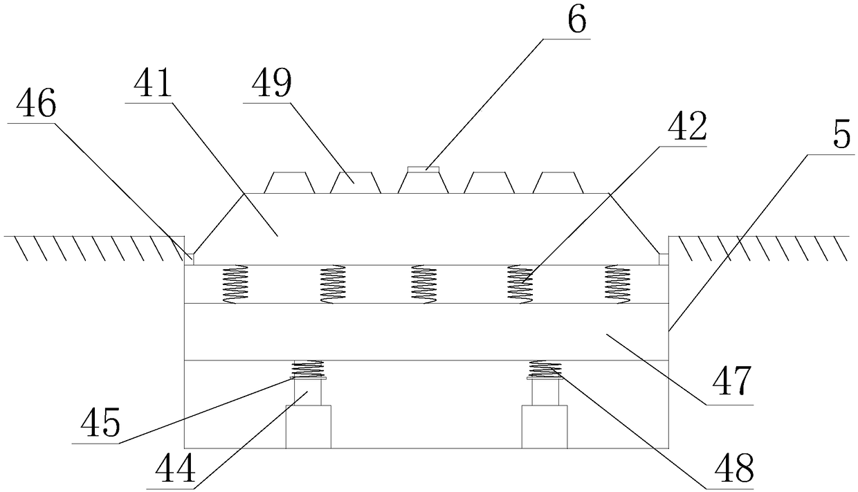
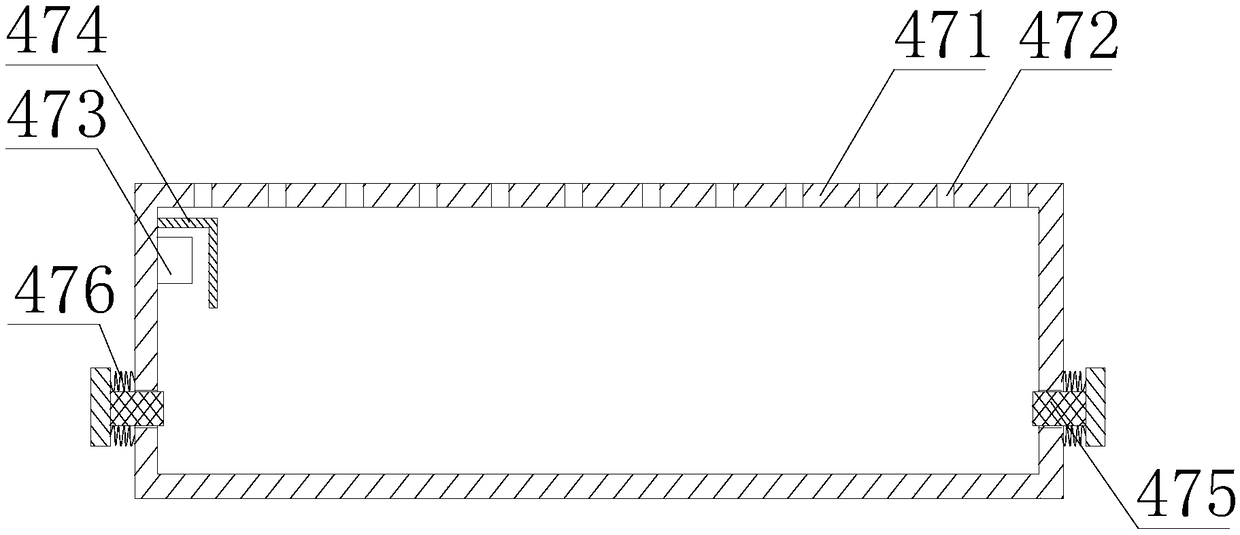
[0045] Such as Figure 2 to Figure 4 The parking lot speed monitoring device shown includes a groove 5 arranged on the lane 1, and a lift-type deceleration mechanism 4 is arranged in the groove 5, and the lift-type deceleration mechanism 4 includes a groove fixed on the bottom surface of the groove 5 A hydraulic cylinder 43 is provided, a support plate 45 is provided on the side wall of the hydraulic cylinder 43, a second spring 48 is provided on the support plate 45, the second spring 48 is sleeved on the outside of the piston rod 44, and the second The top of the spring 48 is connected with a mounting table 47, a deceleration table 41 is arranged above the mounting table 47, the mounting table 47 is connected with the deceleration table 41 through the first spring 42, and a plurality of deceleration gears are arranged side by side on the deceleration table 41 49; the installation platform 47 includes a housing 471, the upper surface of the housing 471 is provided with a plur...

Embodiment 2

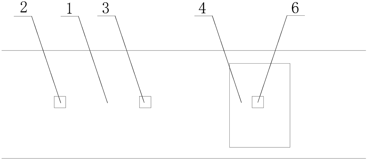
[0050] Such as figure 1 As shown, on the basis of Embodiment 1, it also includes a first infrared range finder 2 and a second infrared range finder 3 arranged on the lane 1, and the second infrared range finder 3 is located at the first infrared range finder. between the instrument 2 and the groove 5; the first infrared range finder 2, the second infrared range finder 3 and the hydraulic cylinder 43 are all electrically connected to the processor of the safety monitoring system; also include a third infrared range finder electrically connected to the processor The range finder 6, the third infrared range finder 6 is installed on the lifting speed reduction mechanism 4; the third infrared range finder 6 is fixed on the reduction gear 49.

[0051] This embodiment can raise the deceleration platform 41 according to the current driving speed of the vehicle and the safety situation in the parking lot, causing strong vibrations. On the one hand, the speed of the vehicle is greatly r...


PUM


Abstract

The invention discloses a parking lot speed monitoring device which comprises a groove arranged in a lane. A lifting type deceleration mechanism is arranged in the groove and includes a hydraulic cylinder fixedly arranged on the bottom surface of the groove, a support plate is arranged on the side wall of the hydraulic cylinder, a second spring is arranged on the support plate and sleeves a pistonrod from outside, a mounting table is connected to the top of the second spring, a deceleration table is arranged above the mounting table, the mounting table is connected with the deceleration tablethrough a first spring, and multiple deceleration teeth are arranged on the deceleration table side by side; the mounting table includes a shell, multiple through holes are formed in the upper surface of the shell, and the through holes are communicated inner and outer spaces of the shell. By the arrangement, the deceleration table can be lifted according to current driving speed of a vehicle andsafety situation in a parking lot, and driving safety in the parking lot is improved.

Description

technical field [0001] The invention relates to a parking lot management system, in particular to a parking lot speed monitoring device. Background technique [0002] Today, when parking spaces are getting tighter, parking lots are widely distributed in hotels, residential areas, parks and other areas. According to the location of the parking lot, the parking lot can be divided into indoor parking lot and open-air parking lot. [0003] The parking lot management system includes vehicle identity judgment, access control, automatic license plate recognition, parking space retrieval, parking space guidance, meeting reminder, image display, vehicle type verification, time calculation, fee collection and verification, voice intercom, automatic card collection (receipt) system. These functions can be flexibly increased or decreased according to actual needs, forming luxury, standard, and economical parking lot management systems and vehicle control systems of different sizes. ...

Claims


Application Information

Patent Timeline
IPC IPC(8): E01F11/00E01F9/529
CPCE01F9/529E01F11/00Y02A20/108
Inventor 梁静
Owner 绵阳鹏志远科技有限公司
Why Eureka
Try Eureka