Device for twisting and disassembling steel wire rope or steel strand

A steel strand and steel wire rope technology, applied in the field of regeneration, can solve the problems of high energy consumption, low efficiency, and inability to realize continuous splitting, etc., and achieve the effect of reliable function, simple structure, and improved splitting efficiency

Active Publication Date: 2020-05-15
CHONGQING VOCATIONAL INST OF ENG +1
View PDF7 Cites 1 Cited by
  • Summary
  • Abstract
  • Description
  • Claims
  • Application Information

AI Technical Summary

Problems solved by technology

[0004] The purpose of the present invention is to provide a device for twisting and splitting steel wire ropes or steel strands to solve the problems that the existing steel wire ropes cannot be disassembled continuously, resulting in low efficiency and high energy consumption. A plurality of steel wire traction mechanisms for pulling steel wire strands or steel wires to pull the steel wire strands or steel wires through the steel wire traction mechanisms to form a rapid split of the steel wire ropes or steel strands, improving the efficiency of splitting, and eliminating the need to The steel wire rope is cut or punched into sections to save kinetic energy consumption

Method used


Image

  • Device for twisting and disassembling steel wire rope or steel strand
  • Device for twisting and disassembling steel wire rope or steel strand
  • Device for twisting and disassembling steel wire rope or steel strand

Examples


Embodiment 1

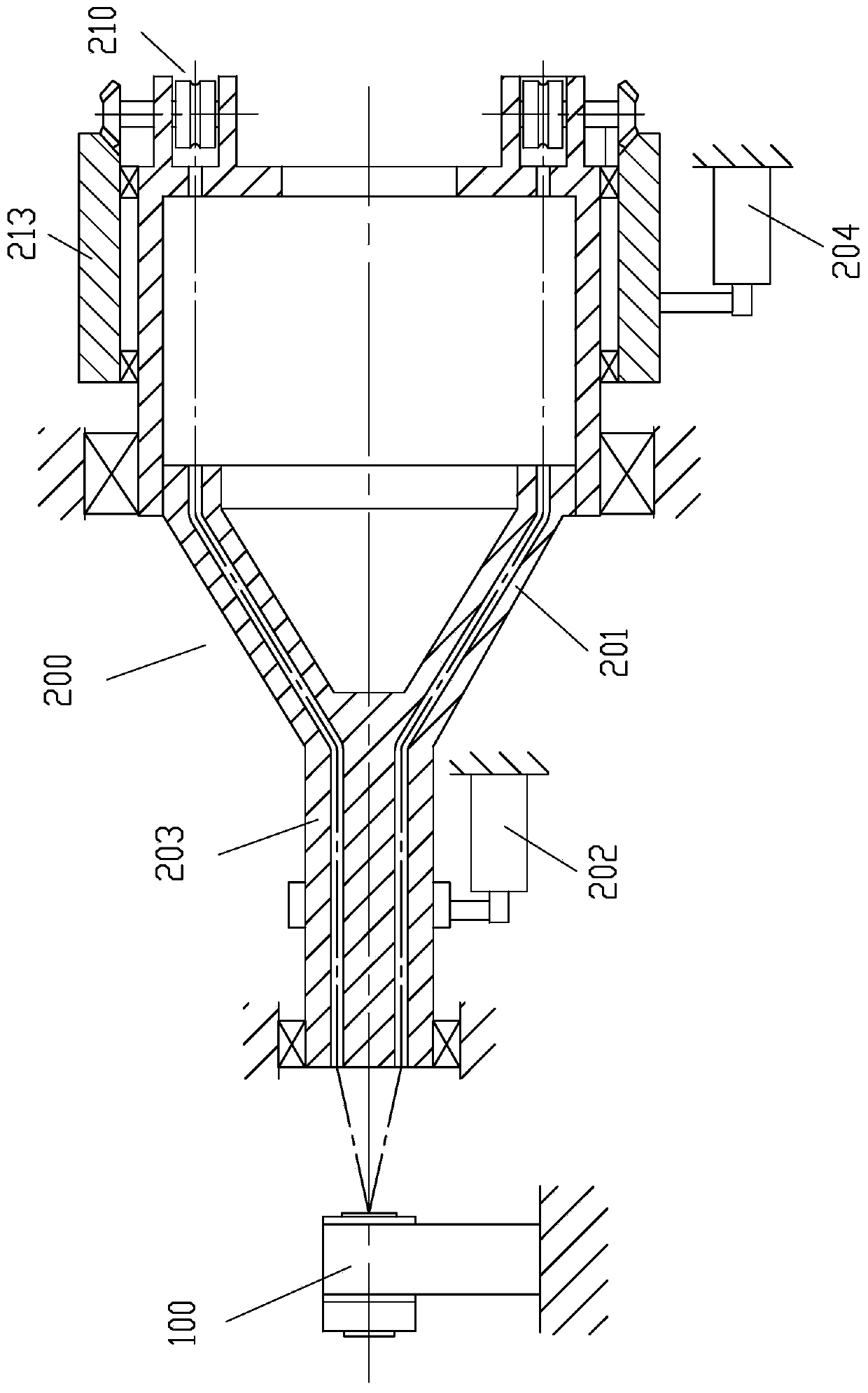
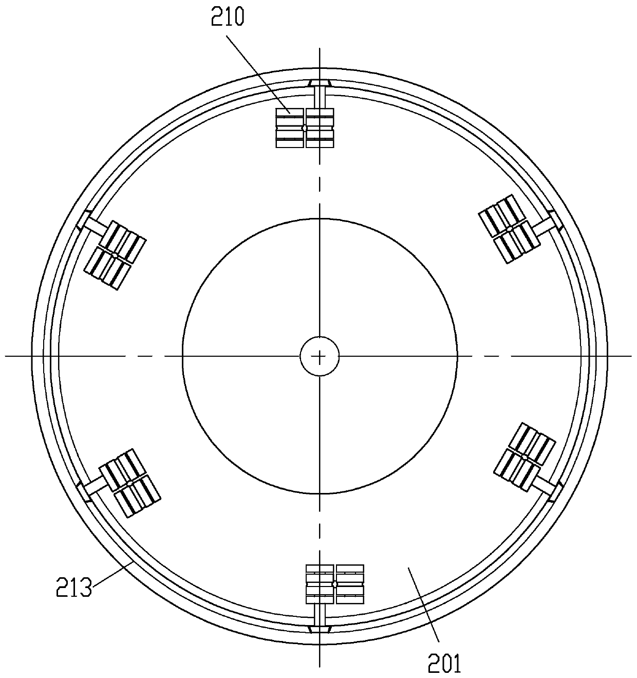
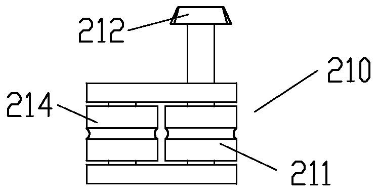
[0025] Example 1, see figure 1 , figure 2 , image 3 , a device for twisting and splitting steel wire ropes or steel strands, including a guiding device 100 and a splitting device 200, the guiding cylinder provided with the guiding device 100 can rotate intermittently, so as to split the steel wire rope or steel strand passing through the guiding cylinder while twisting When passing through the section, the steel wire rope or steel strand is prevented from twisting at the exit of the guide cylinder; the dismantling device 200 is a turntable structure capable of rotating in the direction of dismantling each strand of the steel rope or each steel wire of the steel strand, and on the turntable body 201 There are multiple steel wire traction mechanisms for pulling steel wire strands or steel wires.

[0026] Wherein, the guide hole wall in the guide cylinder is provided with spirally distributed protrusions, the guide cylinder is rotatably arranged on the base 1, and the guide c...

Embodiment 2

[0031] Example 2, see Image 6 , the sun gear is made up of a sun gear 213a, the sun gear 213a is connected with the second rotary drive source 204, and the sun gear 213a is rotatably arranged on the third fixed member of the frame class.

[0032] The rest of the structure of this embodiment is the same as that of Embodiment 1, and will not be repeated here.

Embodiment 3

[0033] Example 3, see Figure 7 , the brake device also includes an elastic element 8; the elastic force of the elastic element 8 and the electromagnetic force of the electromagnetic coil 4 coordinate and cooperate to form the braking and release of the brake on the guide cylinder. Wherein, braking device also comprises braking ring 5, and the through hole in the middle part of braking ring 5 can pass through freely for steel wire rope, and braking ring 5 is only movable and is coaxially arranged at one end of guide tube, and braking ring 5 is formed by described The elastic force of the elastic element 8 and the electromagnetic force of the electromagnetic coil 4 drive the movement; a jaw clutch structure is formed between the outer cylinder 3 of the guide cylinder and the brake ring 5; the elastic force of the elastic element 8 pushes the jaw clutch Combining to form a brake on the guide cylinder, the electromagnetic force generated after the electromagnetic coil 4 is energi...


PUM


Abstract

The invention discloses a device for twisting and disassembling a steel wire rope or a steel strand. The device comprises a guide device and a disassembling device, and a guide cylinder arranged on the guide device can intermittently rotate, so that the steel wire rope or the steel strand is prevented from twisting at an outlet of the guide cylinder when the steel wire rope or the steel strand penetrating out of the guide cylinder is twisted and diassembled. The disassembling device is of a rotary disc structure capable of rotating in the direction of disassembling all strands of steel wire ropes or all steel wires of steel strands, and a plurality of steel wire traction mechanisms for pulling the steel wire strands or the steel wires are arranged on a rotary disc body. The device has thebeneficial effects that the steel wire rope or the steel strand can be continuously disassembled into single strands or single wires, the steel wire rope is prevented from being cut off before disassembly, and the energy consumption is reduced.

Description

technical field [0001] The invention relates to the technical field of regeneration, in particular to a device for twisting and splitting steel wire ropes or steel strands. Background technique [0002] The steel wire rope has a multi-strand helical winding structure, and the steel wire in each strand is also wound into strands in a helical winding manner. The steel strand is helically wound together by multiple steel wires, and the structure is the same as the strands of the steel wire rope; in comparison, the steel wire diameter of the steel wire rope Usually thinner, steel strands have thicker wire diameters. Steel wire ropes and steel strands are widely used in many fields of industrial and agricultural production and construction power. However, after the steel wire rope or steel strand has been used for a certain period of time, the steel wire will usually break, and the steel wire rope may also have broken strands or ropes. was scrapped. Therefore, in the long-term...

Claims


Application Information

Patent Timeline
Patent Type & Authority Applications(China)
IPC IPC(8): H01B15/00
CPCH01B15/00Y02W30/82
Inventor 王洁刘玉玺马江涛王晶晶杨永平王钰峰邓榆焓吴冬
Owner CHONGQING VOCATIONAL INST OF ENG
Why Eureka
Try Eureka