Air pressure water discharging device

A drainer and air pressure technology, which is applied in the direction of pressure pumps, machines/engines, gas/liquid distribution and storage, etc., can solve problems such as inability to complete drainage tasks, failure, and small price NPSH

Pending Publication Date: 2020-05-19
FOSHAN DEZHONG PHARMA MACHINERY
View PDF0 Cites 1 Cited by
  • Summary
  • Abstract
  • Description
  • Claims
  • Application Information

AI Technical Summary

Problems solved by technology

This method also has certain disadvantages. It is necessary to choose a more expensive pump with a particularly small NPSH. During operation, if there is an air leak in front of the pump, the drain pump will be evacuated or the negative pressure generated by the pump will be generated when the mechanical seal of the pump is worn. The negative pressure of the small vacuum system cannot complete the drainage task, and the entire vacuum drainage system fails immediately

Method used


Image

  • Air pressure water discharging device
  • Air pressure water discharging device

Examples


Embodiment 1

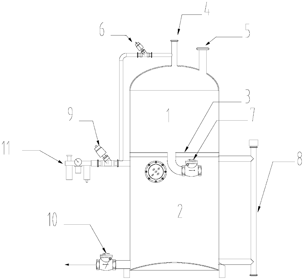
[0023] Such as figure 1 Shown is an air pressure automatic drainage device, which includes a water storage chamber, a drainage chamber and an air pressure automatic control part. The water storage chamber 1 and the drainage chamber 2 are separated into upper and lower layers by upper and lower chamber partitions 3 . The upper water storage chamber 1 is terminated with a vacuum port 4 connected to the system vacuum and a condensed water port 5 . The vacuum is connected with the lower drainage cavity 2 through the normally open vacuum valve 6, so that the lower drainage cavity 2 maintains a negative pressure before the water is full. Condensed water flows into the lower drainage chamber 2 through the normally open water storage check valve 7 installed in the center of the upper and lower chamber partitions 3 .

[0024] When the drainage chamber 2 is full of water, the water level controller 8 sends a water-full command, closes the vacuum valve 6, and opens the compressed air v...

Embodiment 2

[0027] Such as figure 1 The air pressure drain shown includes a cylinder body, and the inner chamber of the cylinder body is divided into an upper water storage chamber 1 and a drainage chamber 2 through an upper and lower chamber partition 3 in the middle, and a single unit is installed on the upper and lower chamber partition 3 To the water passing device; the outside of the cylinder is provided with a vacuum connecting pipe whose two ends are connected to the water storage chamber 1 and the drainage chamber 2 respectively.

[0028] The one-way water passing device includes a downwardly recessed water-guiding structure on the upper and lower chamber partitions 3 , and a water-storage one-way valve 7 is fixed at the free end of the water-guiding structure.

[0029] The upper part of the cylinder body is a convex dome structure, and the side of the dome structure is connected with a condensation water interface 5 .

[0030] A vacuum port 4 is communicated at the center of the...


PUM


Abstract

The invention provides an air pressure water discharging device. A cylinder is included. An inner cavity of the cylinder is divided by a middle upper-lower cavity partition plate into an upper water storage cavity and a water discharging cavity, and the upper-lower cavity partition plate is provided with a one-way water passing device. The outer portion of the cylinder is provided with a vacuum communication pipe, wherein the two ends of the vacuum communication pipe communicate with the water storage cavity and the water discharging cavity correspondingly. No mechanical rotation component isadopted in the air pressure water discharging device, and an air pressure rapid and simple water discharging method is adopted. Water can be directly discharged to the high position of dozens of meters after being discharged from a vacuum system, and the problems in the prior art are solved.

Description

technical field [0001] The invention relates to the field of pneumatic drainage, in particular to a pneumatic drainage device. Background technique [0002] A system operating in a vacuum environment should discharge condensed water, waste water or liquid products generated in the process out of the vacuum system and to a high level. This is a bit of a hassle. For example, the current domestic vacuum concentration production process needs to discharge the condensed water generated. Most of them use a closed storage tank connected to the vacuum system to collect the condensed water. After the tank is emptied, the drain can only be opened after the closed storage tank reaches normal pressure, and the condensed water will flow out slowly. In order to prepare for the next drainage, the previous procedure must be reversed once, that is, close the drain, close the emptying, and finally open the condensate inlet of the vacuum system. If you want to drain the water to a high leve...

Claims


Application Information

Patent Timeline
Patent Type & Authority Applications(China)
IPC IPC(8): F04F1/06F17D1/08F17D3/01
CPCF04F1/06F17D1/08F17D3/01
Inventor 杨许作
Owner FOSHAN DEZHONG PHARMA MACHINERY
Why Eureka
Try Eureka