
Outdoor waterproof power cabinet

A power cabinet and shell technology, applied in electrical components, substation/distribution device shell, substation/switch layout details, etc., can solve the problems of submerged power cabinet base, rainwater sputtering, etc., to avoid rainwater damage and structure stability , the effect of stable lifting

Inactive Publication Date: 2020-05-19
纪发展
View PDF6 Cites 3 Cited by
  • Summary
  • Abstract
  • Description
  • Claims
  • Application Information

AI Technical Summary

Problems solved by technology

Most of the existing outdoor power cabinets are equipped with rain-proof baffles to prevent rainwater from splashing into the power cabinet to short-circuit the electrical components and cause damage to the electrical components.
When there is heavy rain outside, if the drainage system is blocked and water accumulates on the road, this part of the accumulated water may flood the base of the power cabinet, causing other rainwater to splash into the inside of the power cabinet. In order to prevent this from happening, it is necessary to design Develop a power cabinet that can automatically adjust the height of the up and down according to the rain

Method used


Image

  • Outdoor waterproof power cabinet
  • Outdoor waterproof power cabinet
  • Outdoor waterproof power cabinet

Examples


Embodiment 1

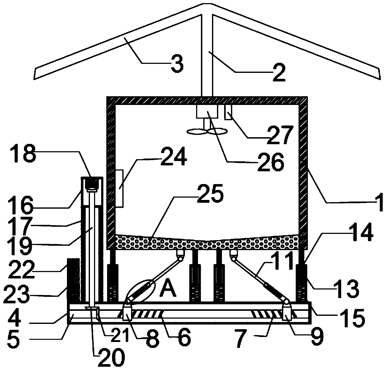
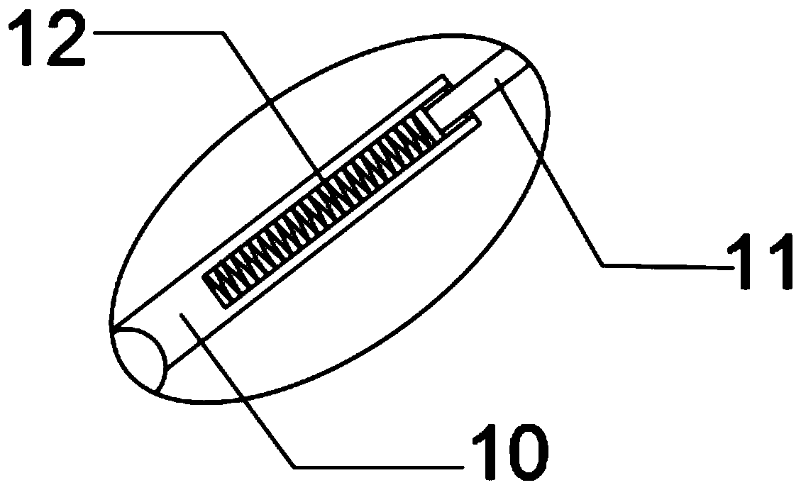
[0018] See Figure 1-2 This embodiment provides an outdoor waterproof power cabinet, which includes a power cabinet shell 1, a rain shield bracket 2 and a rain shield 3; the power cabinet shell 1 is provided with power control elements; the power cabinet shell 1 A rain shield 3 used to block rain is fixed on the upper side by a rain shield bracket 2; it also includes a base 4, a control device 24, a driving mechanism and a lifting mechanism; the lifting mechanism includes a screw rod 5, a first sleeve 8, a second The sleeve 9 and the connecting rod mechanism; the screw rod 5 is rotatably arranged in the base 4 and the screw rod 5 is symmetrically provided with a first sliding groove 6 and a second sliding groove 7 with opposite rotation directions; the first sliding groove 6 and the second chute 7 are respectively provided with a first sleeve 8 and a second sleeve 9 which are matched with the same structure; the upper ends of the first sleeve 8 and the second sleeve 9 are hinge...

Embodiment 2

[0026] This embodiment is further improved on the basis of embodiment 1. The improvement is: the top of the inner wall of the power cabinet housing 1 is also provided with a fan 26 and a heating block 27; the fan 26 and the heating block 27 and the control device 24 Electrical connection; in this way, when there is water on the road, the control device 24 controls the fan 26 and the heating block 27 to work. At this time, the hot air is discharged from the bottom filter hole of the power cabinet shell 1, so as to ensure the inside of the power cabinet shell 1 Dryness.


PUM


Abstract

The invention discloses an outdoor waterproof power cabinet. The outdoor waterproof power cabinet comprises a lifting mechanism and a driving mechanism; a rainwater sensing mechanism is arranged on one side of the driving mechanism; and the rainwater sensing mechanism comprises a rainwater sensing device shell, absorbent cotton and two wires. The rainwater sensing device shell is fixed to one sideof the base, and a plurality of small holes for water inflow are formed in the lower half portion of the rainwater sensing device shell. Water absorption cotton is placed in the rainwater sensing device shell; the top of the absorbent cotton is provided with two wires electrically connected with the control device, and the two wires are not in contact with each other. The control device is electrically connected with the driving mechanism. According to the outdoor waterproof power cabinet, the lifting mechanism, the rainwater sensing mechanism and the control device are arranged, so that thelifting of the power cabinet can be automatically controlled, and electrical elements are prevented from being damaged by rainwater; and by arranging a connecting rod mechanism and a connecting mechanism, the electric power cabinet is more stable during lifting, so that the structure of the device is more stable.

Description

Technical field [0001] The invention relates to a power cabinet, in particular to an outdoor waterproof power cabinet. Background technique [0002] In urban development planning, it is necessary to set up power cabinets outdoors for the transfer and control of power. However, most of the existing outdoor power cabinets are equipped with rain-proof baffles to prevent rainwater from splashing into the power cabinet and short-circuit the electrical components, resulting in damage to the electrical components. When the rain outside is heavy, if the drainage system is blocked and the road surface water is blocked, this part of the accumulated water may flood the base of the power cabinet and cause other rainwater to splash into the power cabinet. In order to prevent this from happening, design is required A power cabinet that can automatically adjust the up and down height according to rain conditions. Summary of the invention [0003] The object of the present invention is to provi...

Claims


Application Information

Patent Timeline
IPC IPC(8): H02B1/30H02B1/28
CPCH02B1/28H02B1/303
Inventor 纪发展
Owner 纪发展
Learn More