
Wire twisting mechanism for rotating power plug part by 180 degrees

A twisting mechanism and power plug technology, which is applied in the field of power cord production, can solve problems such as low production efficiency, improper twisting, looseness, etc.

Inactive Publication Date: 2020-05-22
浙江海宁普赛自动化科技有限公司
View PDF2 Cites 0 Cited by
  • Summary
  • Abstract
  • Description
  • Claims
  • Application Information

AI Technical Summary

Problems solved by technology

When manually twisting the wire, it is easy to have the phenomenon that the twisting wire is not in place or the rotation angle of the twisted wire is too large. When the rotation angle is too large, the welding part of the insertion piece and the wire part will produce a large force, and in severe cases, it will loosen or break.
[0004] The traditional manual twisting method not only makes the injection molding quality of the three-core power plug susceptible to artificial factors, but also requires a lot of manpower and space to use manual twisting. Compared with mechanical automatic twisting equipment, the production efficiency is low and the production cost is increased.

Method used


Image

  • Wire twisting mechanism for rotating power plug part by 180 degrees
  • Wire twisting mechanism for rotating power plug part by 180 degrees
  • Wire twisting mechanism for rotating power plug part by 180 degrees

Examples


Embodiment Construction

[0035] The specific implementation manners of the present invention will be further described in detail below in conjunction with the accompanying drawings and embodiments. The following examples are used to illustrate the present invention, but are not intended to limit the scope of the present invention.

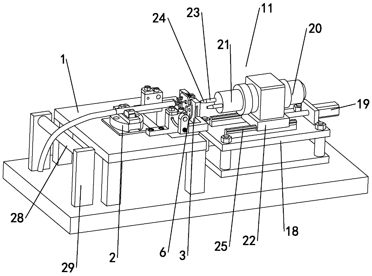
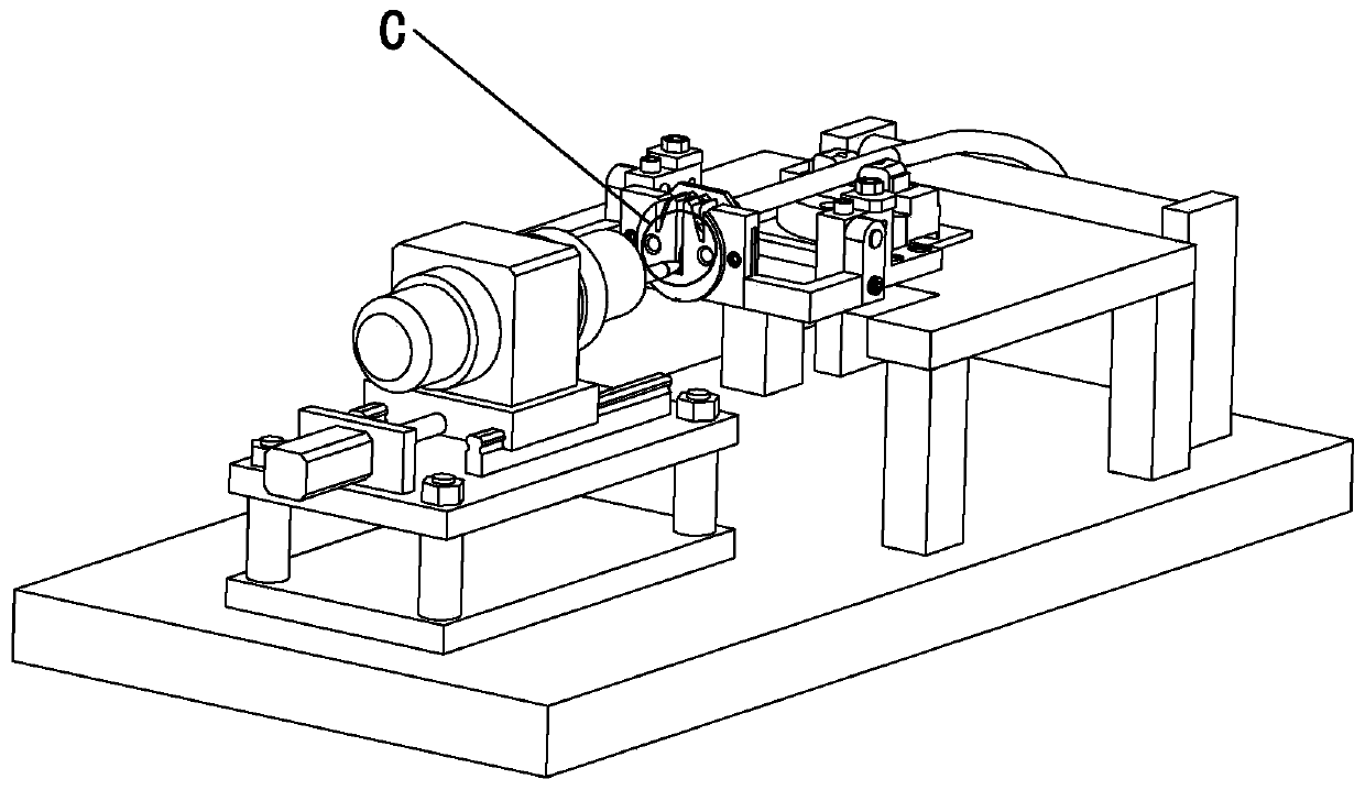
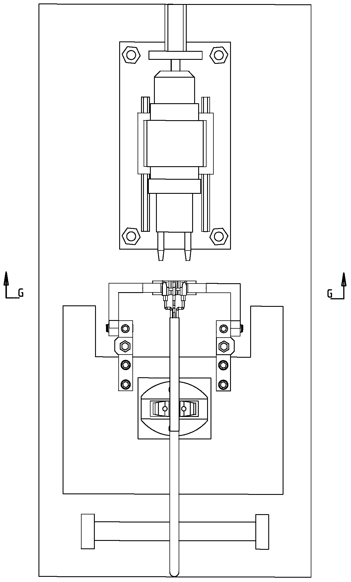
[0036] The following reference Figure 1 to Figure 8 The present invention will be described.

[0037] A twisting mechanism for the power plug part to rotate 180°, including a base 1, the shape of the base 1 is rectangular, brackets 29 are arranged on both sides of the base 1, and a bracket 29 is arranged on the side of the base 1 far away from the plug part fixing seat 3. Wire hanging rod 28, the two ends of wire hanging rod 28 are fixedly connected on the support 29 by screws.

[0038] The base 1 is provided with a power cord fixing seat 2 and a plug part fixing seat 3, the power cord fixing seat 2 is fixed on the middle back of the upper surface of the base 1 by screw...


PUM


Abstract

The invention discloses a wire twisting mechanism for rotating a power plug part by 180 degrees. The wire twisting mechanism comprises a base, and a power line fixing seat and a plug part fixing seatare arranged on the base; the plug part fixing seat is rectangular, and a circular groove is formed in the middle of the plug part fixing seat; a first opening is formed in the upper end of the circular groove, and an inserting piece fixing block is arranged in the groove; and a live wire inserting piece groove, a zero line inserting piece groove and a ground wire inserting piece groove are formedin the inserting piece fixing block, openings in the upper ends of the live wire inserting piece groove, the zero line inserting piece groove and the ground wire inserting piece groove are communicated with the first opening, two rotating through holes are symmetrically formed in the two sides of the middle of the inserting piece fixing block, and a rotating driving mechanism is arranged on the side, away from the power line fixing base, of the inserting piece fixing block. The wire twisting mechanism can twist three connecting wires behind three inserting pieces of the three-core power plug,the wire twisting angle meets the production requirement, injection molding can be conducted more conveniently, it is guaranteed that the injection molding quality is high, and meanwhile high wire twisting efficiency is achieved.

Description

technical field [0001] The invention relates to the technical field of power cord production, in particular to a twisting mechanism for a power plug part to rotate 180°. Background technique [0002] Power plug refers to the device that connects electrical appliances and other devices to the power supply. The existing power plug usually uses injection molding to press the plug and wire together through high temperature and high pressure. Once formed, it cannot be assembled and disassembled. The power plug molded by injection molding It has the advantages of stability and safety. [0003] When the three-core power plug is injected, the live wire, neutral wire and ground wire connected behind the three inserts will be tilted or skewed because they are not limited, which will increase the difficulty of injection molding of the power plug. In severe cases, some wires will be damaged. Exposure to the outside of the injection molded plug affects the normal use of the plug. Theref...

Claims


Application Information

Patent Timeline
IPC IPC(8): H01R43/20
CPCH01R43/20
Inventor 余崇威潘克飞
Owner 浙江海宁普赛自动化科技有限公司
Learn More