Optical module parameter debugging method, storage medium and terminal equipment

A technology of parameter debugging and optical modules, which is applied in character and pattern recognition, electromagnetic wave transmission systems, instruments, etc., can solve the problems of low debugging efficiency, failure to complete in one step, and many adjustment times, so as to improve debugging efficiency and avoid repeated debugging Effect

Active Publication Date: 2020-05-22
深圳市欧深特信息技术有限公司
View PDF10 Cites 1 Cited by
  • Summary
  • Abstract
  • Description
  • Claims
  • Application Information

AI Technical Summary

Problems solved by technology

In the debugging process, once the pre-set initial value cannot be adjusted successfully, the adjustment process of the dichotomy method only adopts a fixed step size or a simple dichotomous step size to approach one by one, which cannot be achieved in one step.

Method used


Image

  • Optical module parameter debugging method, storage medium and terminal equipment
  • Optical module parameter debugging method, storage medium and terminal equipment
  • Optical module parameter debugging method, storage medium and terminal equipment

Examples


Embodiment Construction

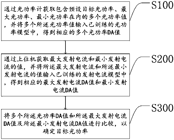
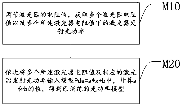
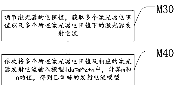
[0048] In view of the problems in the prior art, the present invention provides an optical module parameter debugging method, a storage medium and a terminal device. The DA value of the target optical power is directly calculated by the method of training the model, which avoids repeated debugging and improves the debugging efficiency.

[0049] The specific implementation of the present invention is for the convenience of a more detailed description of the technical concept of the present invention, the technical problems to be solved, the technical features constituting the technical solution and the technical effects brought about. It should be noted that the explanations for these implementations do not constitute a limitation to the protection scope of the present invention. In addition, the technical features involved in the embodiments described below may be combined with each other as long as they do not conflict with each other. In addition, the terms in the present in...


PUM

PropertyMeasurementUnit
electrical resistanceaaaaaaaaaa

Abstract

The invention discloses an optical module parameter debugging method, a storage medium and terminal equipment. The method comprises the steps of acquiring a plurality of optical power values includingpreset target optical power, maximum optical power and minimum optical power through an optical power meter, and inputting the plurality of optical power values into a trained optical power model toobtain a plurality of corresponding optical power DA values; obtaining the values of the maximum emission current and the minimum emission current through an upper computer, and inputting the values of the maximum emission current and the minimum emission current into a trained emission current model to obtain a corresponding maximum emission current DA value and a corresponding minimum emission current DA value; and comparing the plurality of optical power DA values with the maximum emission current DA value and the minimum emission current DA value to determine target optical power. According to the method, the DA value of the target optical power is directly calculated through a model training method; repeated debugging is avoided; and the debugging efficiency is improved.

Description

technical field [0001] The invention relates to the field of optical parameter debugging, in particular to an optical module parameter debugging method, storage medium and terminal equipment. Background technique [0002] In the prior art, methods for debugging optical parameters (optical power and extinction ratio) of an optical module are generally dichotomous. In the debugging process, once the pre-set initial value cannot be adjusted successfully, the adjustment process of the dichotomy method only adopts a fixed step size or a simple dichotomous step size to approach one by one, which cannot be achieved in one step. . [0003] Thereby prior art still needs to improve and improve. Contents of the invention [0004] In view of the shortcomings of the above-mentioned prior art, the object of the present invention is to provide a method for debugging optical module parameters, storage media and terminal equipment, and directly calculate the DA value of the target optica...

Claims


Application Information

Patent Timeline
Patent Type & Authority Applications(China)
IPC IPC(8): H04B10/564G06K9/62
CPCH04B10/564G06F18/214
Inventor 苏恒毅
Owner 深圳市欧深特信息技术有限公司
Why Eureka
Try Eureka