Charging pile with automatic wire take-up function

A technology of charging piles and functions, applied in the field of charging piles with automatic take-up function, which can solve the problems of complicated and difficult device installation, lack of automatic take-up function, damaged charging lines, etc., to achieve easy disassembly, easy installation, and avoid rot Effect

Inactive Publication Date: 2020-05-26
薛成
View PDF0 Cites 1 Cited by
  • Summary
  • Abstract
  • Description
  • Claims
  • Application Information

AI Technical Summary

Problems solved by technology

[0002] The function of the charging pile is similar to the fuel dispenser in the gas station. It can be fixed on the ground or wall, and installed in the parking lot or charging station of public buildings and residential areas. It can charge various types of electric vehicles according to different voltage levels. The charging pile The input end of the battery is directly connected to the AC power grid, and the output end is equipped with a charging plug for charging electric vehicles. Charging piles generally provide two charging methods: conventional charging and fast charging. Swipe the card on the computer interactive operation interface to perform the corresponding charging method, charging time, cost data printing and other operations. The display screen of the charging pile can display the charging amount, cost, charging time and other data. The existing device does not have the function of automatic wire collection. Just scattering the charging connectors and charging cables on the ground will easily lead to entanglement of the charging cables and damage caused by rolling. The installation of existing devices is more complicated and difficult.

Method used


Image

  • Charging pile with automatic wire take-up function
  • Charging pile with automatic wire take-up function
  • Charging pile with automatic wire take-up function

Examples


Embodiment Construction

[0017] The following will clearly and completely describe the technical solutions in the embodiments of the present invention with reference to the accompanying drawings in the embodiments of the present invention. Obviously, the described embodiments are only some, not all, embodiments of the present invention. Based on the embodiments of the present invention, all other embodiments obtained by persons of ordinary skill in the art without making creative efforts belong to the protection scope of the present invention.

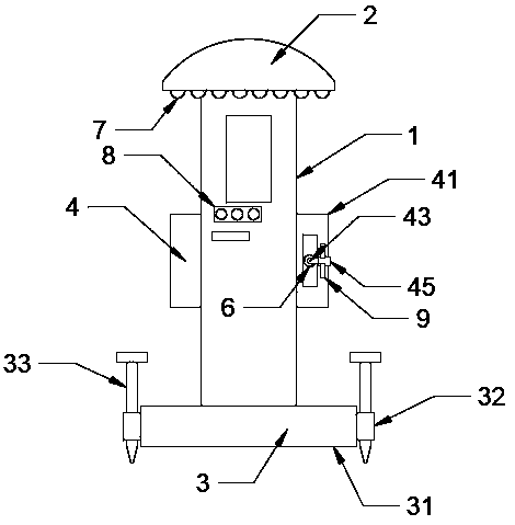
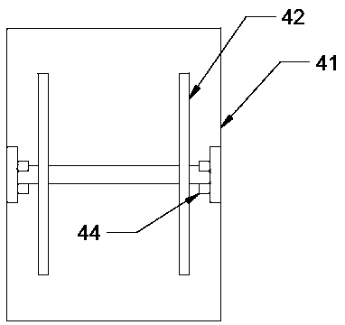
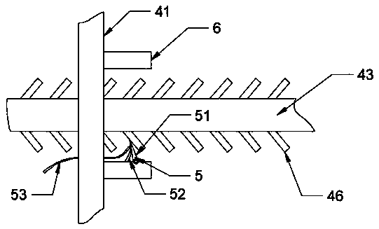
[0018] see Figure 1-3 , the present invention provides a technical solution: a charging pile with automatic wire take-up function, including a charging pile 1, the upper end of the charging pile 1 is provided with a rain shield 2, and the lower end of the charging pile 1 is provided with a mounting mechanism 3. Both sides of the charging pile 1 are provided with a wire take-up mechanism 4, the wire take-up mechanism 4 includes a wire storage box 41, a winding...


PUM


Abstract

The invention discloses a charging pile with an automatic wire take-up function. The charging pile with the automatic wire take-up function comprises a charging pile; a flashing board is arranged at the upper end of the charging pile; a mounting mechanism is arranged at the lower end of the charging pile; wire take-up mechanisms are arranged on the two sides of the charging pile correspondingly; each wire take-up mechanism comprises a wire storage box, a wire spool, a charging wire and a fixing mechanism; the wire storage boxes are installed on the two sides of the charging pile; an installation hole is formed in the surface of one side of each wire storage box in a clamped mode; each wire spool is movably installed on the inner side of the corresponding wire storage box through a bearing;torsional springs are arranged on the two sides of each wire spool respectively; one end of each torsional spring is fixedly connected with a rotating shaft where the corresponding wire spool is located, and the other end of each torsional spring is fixedly connected with the side wall of the corresponding wire storage box. According to the charging pile with the automatic wire take-up function of the invention, clamping pieces are pulled back by pulling ropes in fixing mechanisms, so that the clamping pieces are separated from clamping strips on the charging wires of the wire take-up mechanisms; the wire spools are driven by the torsional springs to rotate, so that the charging wires are driven to be wound on the wire spools; and therefore, the automatic take-up of the charging wires isachieved.

Description

technical field [0001] The invention relates to the technical field of charging pile electronic equipment, in particular to a charging pile with an automatic wire-retracting function. Background technique [0002] The function of the charging pile is similar to the fuel dispenser in the gas station. It can be fixed on the ground or wall, and installed in the parking lot or charging station of public buildings and residential areas. It can charge various types of electric vehicles according to different voltage levels. The charging pile The input end of the battery is directly connected to the AC power grid, and the output end is equipped with a charging plug for charging electric vehicles. Charging piles generally provide two charging methods: conventional charging and fast charging. Swipe the card on the computer interactive operation interface to perform the corresponding charging method, charging time, cost data printing and other operations. The display screen of the cha...

Claims


Application Information

Patent Timeline
Patent Type & Authority Applications(China)
IPC IPC(8): B60L53/18B60L53/31B65H75/38B65H75/44
CPCH01R13/72Y02T10/70Y02T10/7072Y02T90/12Y02T90/14
Inventor 薛成
Owner 薛成
Why Eureka
Try Eureka