Chamfered plastic floor
A technology of plastic flooring and chamfering, which is applied to floors, insulation layers, buildings, etc., and can solve problems such as easy accumulation of dust and debris, troublesome cleaning, etc.
- Summary
- Abstract
- Description
- Claims
- Application Information
AI Technical Summary
Problems solved by technology
Method used
Image
Examples
Embodiment 1
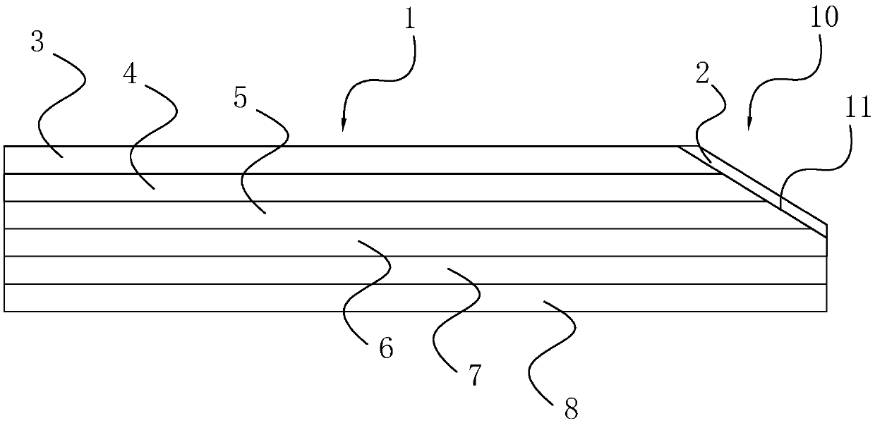
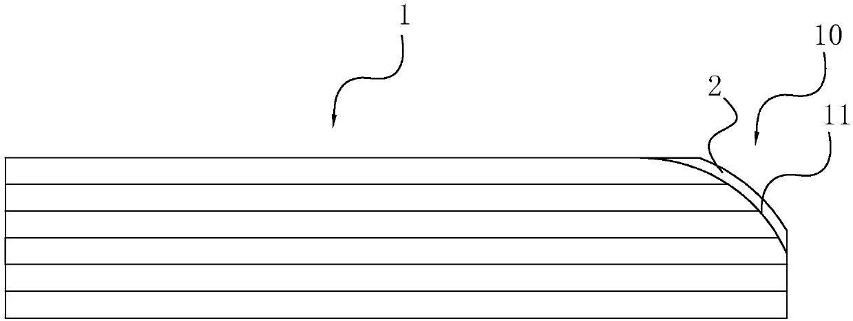
[0040] A chamfered plastic floor is formed by splicing a plurality of substrates 1. At least one edge of the upper surface of the substrate 1 is provided with a surface descending portion 11, and the surface descending portion 11 is arranged along the length direction of the edge of the substrate 1. A boundary area 10 is formed by splicing adjacent substrates 1 at the surface descending portions 11 . The surface descending portions 11 of adjacent substrates 1 together constitute the surface of the boundary area 10 . The surface of the boundary area 10 is covered with an antifouling layer 2 .
[0041] refer to figure 1 As shown, the base plate 1 is included. The base plate 1 is made of a plastic material. The base plate 1 is rectangular, which is a common floor shape, but is not limited to this shape, and can also be a parallelogram, polygon or other shapes of the floor.
[0042] In the actual production process, all four edges of the base plate 1 are provided with surface desc...
Embodiment 2
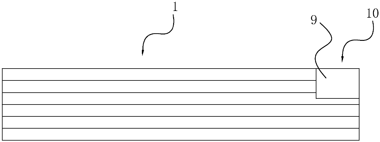
[0048] A chamfered plastic floor, the difference from the first embodiment is that refer to image 3 As shown, a plastic strip 9 is filled in the boundary area 10, and the plastic strip 9 is also made of PVC material. The shape of the plastic strip 9 matches the shape of the boundary area 10, and the plastic strip 9 is embedded in the boundary area 10. When the plastic strip 9 is embedded in the boundary area 10, the outer wall of the plastic strip 9 is close to the surface of the boundary area 10, and the upper surface of the plastic strip 9 is the same height as the upper surface of the substrate 1 or lower than the substrate 1, and the plastic strip 9 The connection with the demarcation area 10 is by fitting or by gluing.
Embodiment 3
[0050] A chamfered plastic floor, the difference from the first embodiment is that refer to Figure 4 As shown, the boundary area 10 is in the shape of a downwardly concave groove, and the boundary area 10 is formed by excavating part of the material of the substrate 1 downward from the upper surface of the substrate 1 . The width of the demarcation area 10 is 1mm-2mm, and the depth of the demarcation area 10 is 0.5mm-1mm.
[0051] The surface of the boundary area 10 can be coated with an antifouling layer 2 , and the plastic strips 9 can also be embedded in the boundary area 10 to achieve the effect of antifouling and easy cleaning of the boundary area 10 .
PUM
| Property | Measurement | Unit |
|---|---|---|
| width | aaaaa | aaaaa |
| angle | aaaaa | aaaaa |
| depth | aaaaa | aaaaa |
Abstract
Description
Claims
Application Information
 - R&D
- Intellectual Property
- Life Sciences
- Materials
- Tech Scout
- Unparalleled Data Quality
- Higher Quality Content
- 60% Fewer Hallucinations
Browse by: Latest US Patents, China's latest patents, Technical Efficacy Thesaurus, Application Domain, Technology Topic, Popular Technical Reports.
© 2025 PatSnap. All rights reserved.Legal|Privacy policy|Modern Slavery Act Transparency Statement|Sitemap|About US| Contact US: help@patsnap.com


