
Main curvature calculation method for contact rolling path of planetary rolling column lead screw pair

A technology of planetary rollers and calculation methods, which is applied to complex mathematical operations, transmission devices, belts/chains/gears, etc., and can solve problems such as the accuracy of which needs to be verified, the structure of the planetary roller screw pair, and errors are not considered.

Active Publication Date: 2020-05-26
INNER MONGOLIA UNIV OF TECH
View PDF4 Cites 5 Cited by
  • Summary
  • Abstract
  • Description
  • Claims
  • Application Information

AI Technical Summary

Problems solved by technology

[0004] The shortcomings of the existing research methods are: the method of calculating the principal curvature between the contact raceways of the planetary roller screw pair is mainly obtained by the principal curvature analysis method of the ball screw pair by equating the roller thread teeth to a ball sphere. , without considering the actual planetary roller screw pair structure
But in fact, the raceways or thread teeth of the screw, roller and nut are space helical surfaces. For a complex transmission device such as a planetary roller screw pair, the main curvature modeling is based on the idea of ​​the equivalent sphere method. Its

Method used


Image

  • Main curvature calculation method for contact rolling path of planetary rolling column lead screw pair
  • Main curvature calculation method for contact rolling path of planetary rolling column lead screw pair
  • Main curvature calculation method for contact rolling path of planetary rolling column lead screw pair

Examples


Embodiment Construction

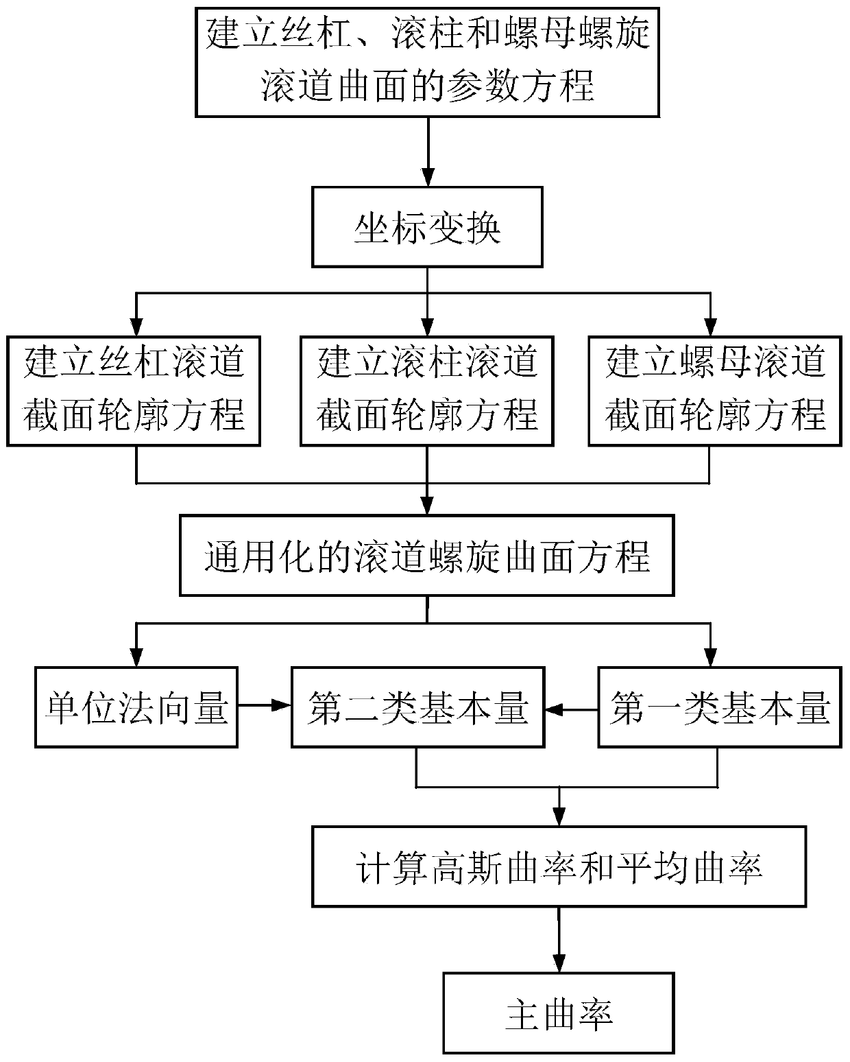
[0114] Such as figure 1 As shown, a method for calculating the main curvature of the contact raceway of a planetary roller screw pair includes the following steps:

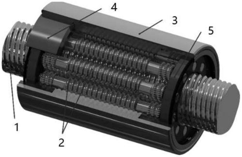
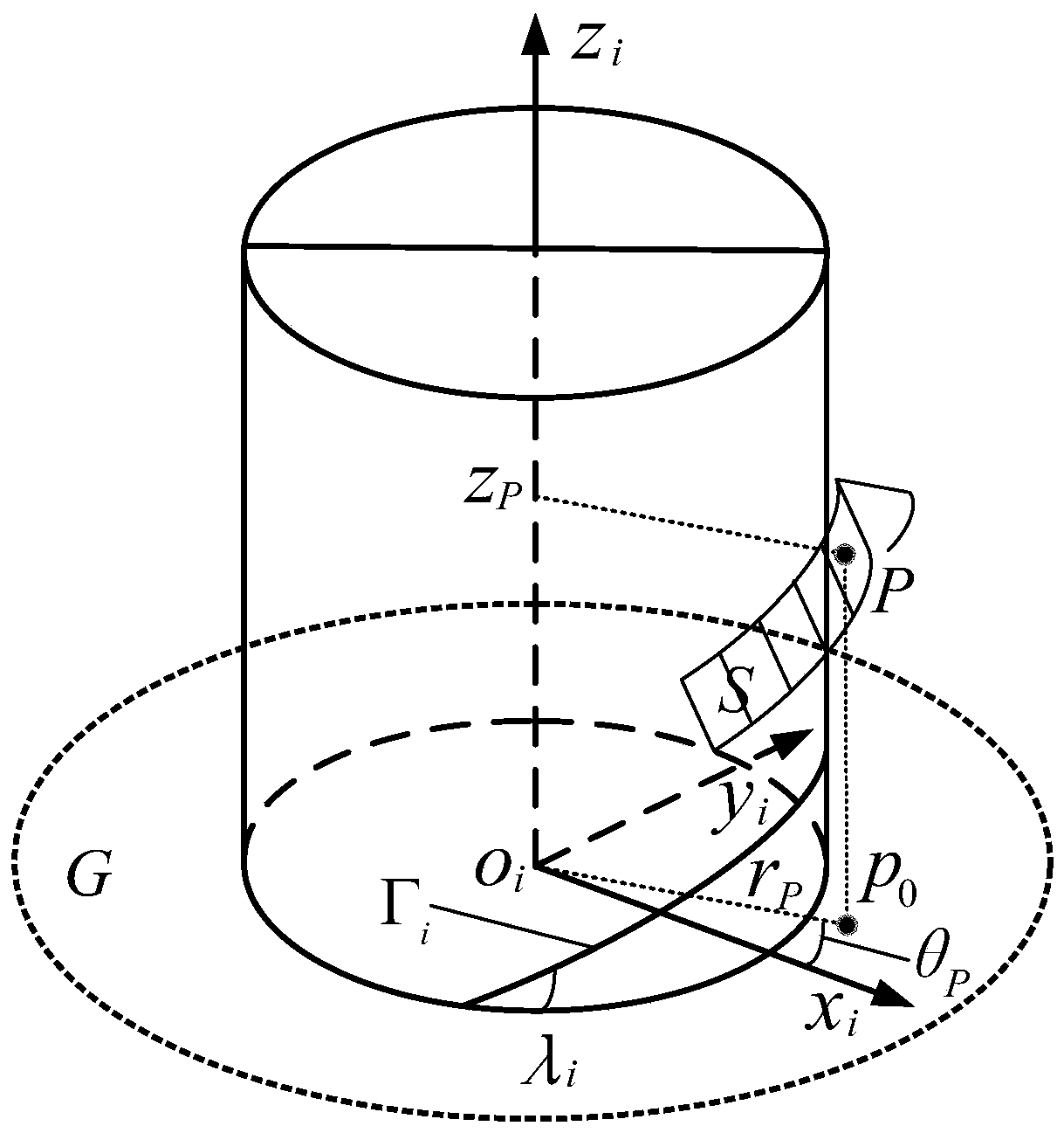
[0115] S1 planetary roller screw pair mainly includes screw 1, roller 2, nut 3, inner ring gear 4 and cage 5, such as figure 2 As shown, among them, the contact raceways of screw 1, roller 2 and nut 3 are used to transmit their motion and power. According to the characteristics of the spiral raceway surface of the screw 1, roller 2 and nut 3 in the planetary roller screw pair, for any point P on the spiral raceway surface S of the screw 1, roller 2 and nut 3, as image 3 As shown, the parametric equation of the spiral raceway surface is established, as shown in formula (Ⅰ):

[0116] F=[r P cosθ P , r P sinθ P , f(r P , θ P )], (r P , θ P )∈G(I);

[0117] Among them, r P and θ P is the parameter coordinate of the surface S, the plane o i x i the y i The polar coordinates of any point in the element...


PUM


Abstract

The invention discloses a main curvature calculation method for a planetary rolling column lead screw pair contact rolling path. The method comprises the steps that a parameter equation of the spiralrolling path curved surfaces of a lead screw, a rolling column and a nut is established; coordinate transformation is carried out; a lead screw rolling path cross section profile equation is established in the normal section of the lead screw; a rolling column rolling path cross section profile equation is established in the normal section of the rolling column; a nut rolling path cross section profile equation is established in the normal section of the nut; a universalized rolling path spiral curved surface equation is established; a general expression of a unit normal vector of any point onthe spiral curved surface of the lead screw, the rolling column or the nut rolling path is acquired; specific expressions of a first type of basic quantity and a second type of basic quantity of thespiral curved surface of the lead screw, the rolling column or the nut rolling path are acquired; and a calculation formula of the Gaussian curvature, the average curvature and the main curvature of the contact rolling path is acquired. With the method, high-precision calculation of the main curvature of the planetary rolling column lead screw pair can be realized, the contact mechanical analysisefficiency of the planetary rolling column lead screw pair can be greatly improved, and a foundation is laid for accurate modeling of subsequent contact stress, contact deformation and frictional wear.

Description

technical field [0001] The invention relates to the technical field of planetary roller screw transmission. Specifically, it is a calculation method for the main curvature of the contact raceway of the planetary roller screw pair. Background technique [0002] Like a ball screw, a planetary roller screw is a rolling screw drive that converts rotary motion into linear motion. As a new type of linear actuator, the planetary roller screw pair has been gradually used in industrial fields such as aerospace, vehicles and precision machine tools due to its outstanding advantages such as large bearing capacity, high precision, long life and impact resistance. The planetary roller screw pair is mainly composed of screw, roller, nut, inner ring gear and cage. Wherein, the lead screw and the nut are of multi-start external triangular thread structure and multi-start internal triangular thread structure respectively, and the roller is of single-start external thread structure, and the...

Claims


Application Information

Patent Timeline
IPC IPC(8): G06F17/11F16H25/22
CPCG06F17/11F16H25/2247Y02T90/00
Inventor 乔冠刘更刘哲铭姜广军崔昭霞张文杰郭世杰
Owner INNER MONGOLIA UNIV OF TECH
Learn More