Display device

A display device and frame technology, applied in the direction of nonlinear optics, optics, instruments, etc., can solve the problems of reducing the display area of ​​the panel, unfavorable product narrow frame requirements, etc., and achieve the effect of reducing the quantity

Pending Publication Date: 2020-05-26
RADIANT OPTO ELECTRONICS SUZHOU
View PDF0 Cites 1 Cited by
  • Summary
  • Abstract
  • Description
  • Claims
  • Application Information

AI Technical Summary

Problems solved by technology

However, the above-mentioned design will cover the surrounding area of ​​the panel, which is not conducive to the narrow bezel requirement of the product, and also reduces the display area of ​​the panel

Method used


Image

  • Display device
  • Display device
  • Display device

Examples


Embodiment Construction

[0023] The features and technical contents of the relevant patent applications of the present invention will be clearly presented in the following detailed description of preferred embodiments with reference to the accompanying drawings. Before going into detail, it should be noted that like components are numbered the same.

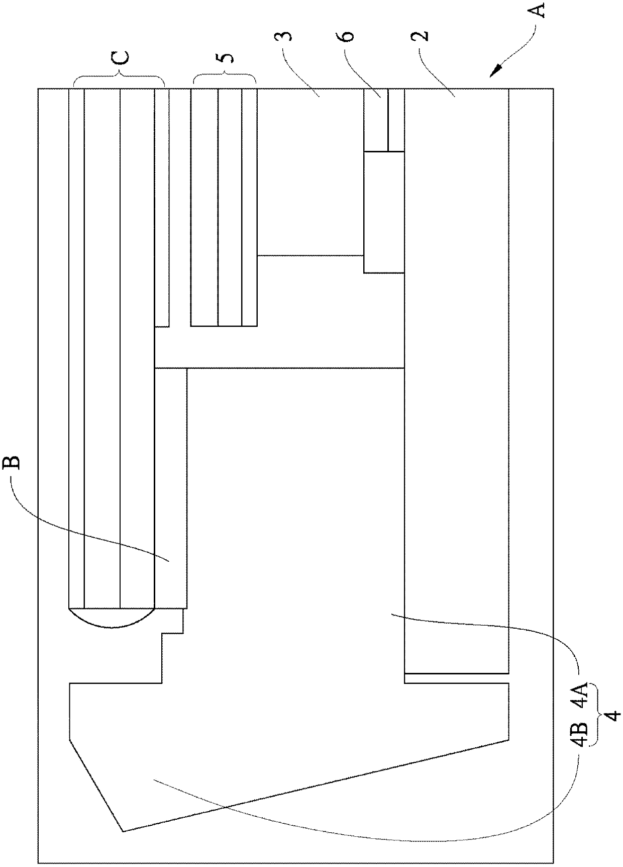
[0024] refer to figure 1 , is a preferred embodiment of the display device of the present invention, which includes a backlight module A, at least one adhesive member B disposed on the backlight module A, and a panel C pasted by the adhesive member B. The backlight module A includes a backplane 2, a light guide plate 3 arranged on the backplane 2, a frame 4 arranged around the backplane 2, a plurality of films 5 stacked on the light guide plate 3, and a light guide plate arranged on the backplane 2. The reflection sheet 6 between the plate 2 and the light guide plate 3 . Because the basic structure of this backlight module A can be understood by those ...


PUM


Abstract

The invention provides a display device. The display device comprises a backlight module, at least one bonding piece arranged on the backlight module, and a panel bonded by the bonding piece. The backlight module comprises a back plate, a light guide plate arranged on the back plate and a frame arranged around the back plate, wherein the frame is provided with a bearing part and a side wall part extending upwards from the periphery of the bearing part, and the frame is formed by splicing at least two borders. The bonding piece is arranged on the bearing part of the frame. The panel is adheredto the bearing part of the frame by the at least one bonding piece and is not shielded by any part of the frame. By means of the structural design, extra connecting pieces do not need to be used between the frames, and the number of assembling assemblies is reduced. And the panel is not shielded by the frame, so that the requirement of a narrow frame is met.

Description

technical field [0001] The invention relates to a light source module, in particular to a display device. Background technique [0002] With the continuous development of backlight display technology, display devices such as liquid crystal displays (Liquid Crystal Display, LCD), as display components, have been widely used in electronic products such as mobile phones and televisions. With the narrower and narrower borders of electronic products and the continuous advancement of technology, the large size and narrower borders of LCD screen displays have increasingly become the mainstream demand of the market. [0003] The narrow border means that the screen area that can be seen under the same size screen is larger and the visual effect is better. Existing display devices generally include: a backplane, a light guide plate, an optical film, a display panel, and a frame surrounding the backplane, and the frame is used to cover and fix the display panel. However, the above-me...

Claims


Application Information

Patent Timeline
Patent Type & Authority Applications(China)
IPC IPC(8): G09F9/00G02F1/1333
CPCG02F1/133308G09F9/00G02F1/133314
Inventor 陈致尧黄镫仪赵永杰
Owner RADIANT OPTO ELECTRONICS SUZHOU
Why Eureka
Try Eureka