Nail pushing plate adaptive to suturing nail, and manufacture method

A technology for pushing nails and suture nails, applied in the field of staplers, can solve problems such as deformation, affecting the effect of suture, etc., and achieve the effects of improving accuracy, ensuring quality, and receiving uniform force

Pending Publication Date: 2020-05-29
JIANGSU JICUI MICRO NANO AUTOMATION SYST & EQUIP TECH RES INST CO LTD
View PDF7 Cites 1 Cited by
  • Summary
  • Abstract
  • Description
  • Claims
  • Application Information

AI Technical Summary

Problems solved by technology

[0003] However, in the prior art, the nail pushing plate tends to deform the U-shaped parallel sides of the staple cartridge during the sliding process, thus affecting the suturing effect

Method used


Image

  • Nail pushing plate adaptive to suturing nail, and manufacture method
  • Nail pushing plate adaptive to suturing nail, and manufacture method
  • Nail pushing plate adaptive to suturing nail, and manufacture method

Examples


Embodiment Construction

[0026] The present invention will be further described below in conjunction with the accompanying drawings and specific embodiments, so that those skilled in the art can better understand the present invention and implement it, but the examples given are not intended to limit the present invention.

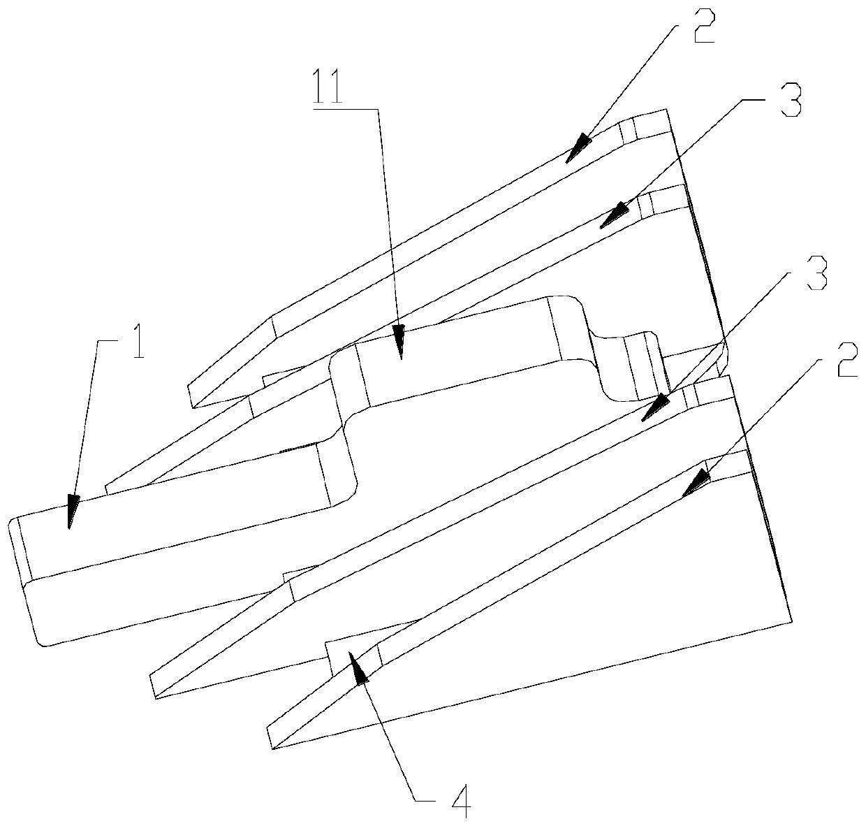
[0027] refer to Figure 1-Figure 4 As shown, an embodiment of a nail pushing plate suitable for staples of the present invention includes a first guide plate 1, two second guide plates 2 and two third guide plates 3 arranged in parallel, and the first guide plate 1 Located in the middle of the nail pushing plate, the two second guide plates 2 are respectively located on both sides of the first guide plate 1, and the two second guide plates 2 are arranged symmetrically with respect to the first guide plate 1; at the same time, the two third guide plates 3 are respectively located on the first guide plate 1 Two sides of a guide plate 1, and two second guide plates 2 are arranged sym...


PUM


Abstract

The invention discloses a nail pushing plate adaptive to a suturing nail, and a manufacture method. The nail pushing plate comprises a first guide plate, two second guide plates and two third guide plates, wherein the first guide plate is positioned in the middle of the nail pushing plate; the two second guide plates are independently positioned on two sides of the first guide plate and are symmetrically arranged; the two third guide plates are independently positioned on two sides of the first guide plate and are symmetrically arranged; the first guide plate comprises an extruded part, wherein the extruded part is positioned on the upper surface of the first guide plate and is used to be embedded in the penetration groove of a nail cabin; the side wall of the first guide plate is fixed with each second guide plate through a connecting plate; and the side wall of each second guide plate is fixed with each third guide plate through a connecting plate. According to the nail pushing plate, two edges of the nail cabin can be kept parallel to improve a suturing effect.

Description

technical field [0001] The invention relates to the field of staplers, in particular to a nail pushing plate adapted to staples and a manufacturing method. Background technique [0002] Staplers quickly and efficiently fasten body tissue by driving fasteners or staples into the tissue. When the tissue is cut and sutured, the pusher plate advances horizontally along the four rows of slots of the staple cartridge. During the advancing process, the pusher plate pushes the pusher piece and the titanium nail in the staple cartridge to move vertically upward, and the head of the titanium nail leaves the staple cartridge to penetrate. The tissue, and then when it touches the anvil of the anastomosis gun, the titanium nail is bent into a B-shape to complete the suturing of the tissue. [0003] However, in the prior art, during the sliding process of the nail pushing plate, the U-shaped parallel sides of the staple cartridge are easily deformed by force, thereby affecting the effect...

Claims


Application Information

Patent Timeline
Patent Type & Authority Applications(China)
IPC IPC(8): A61B17/072
CPCA61B17/072A61B2017/07278A61B2017/00526
Inventor 汝长海李忻朱军辉靳振伟王飞龙
Owner JIANGSU JICUI MICRO NANO AUTOMATION SYST & EQUIP TECH RES INST CO LTD
Why Eureka
Try Eureka