Cassette handlers and mobile terminals
A technology of loading and unloading device and card tray, applied in the field of communication, can solve the problems of complicated loading and unloading process of card tray, inconvenient operation, etc., and achieve the effects of improving user experience, saving manufacturing cost, and preventing movement.
- Summary
- Abstract
- Description
- Claims
- Application Information
AI Technical Summary
Problems solved by technology
Method used
Image
Examples
Embodiment 1
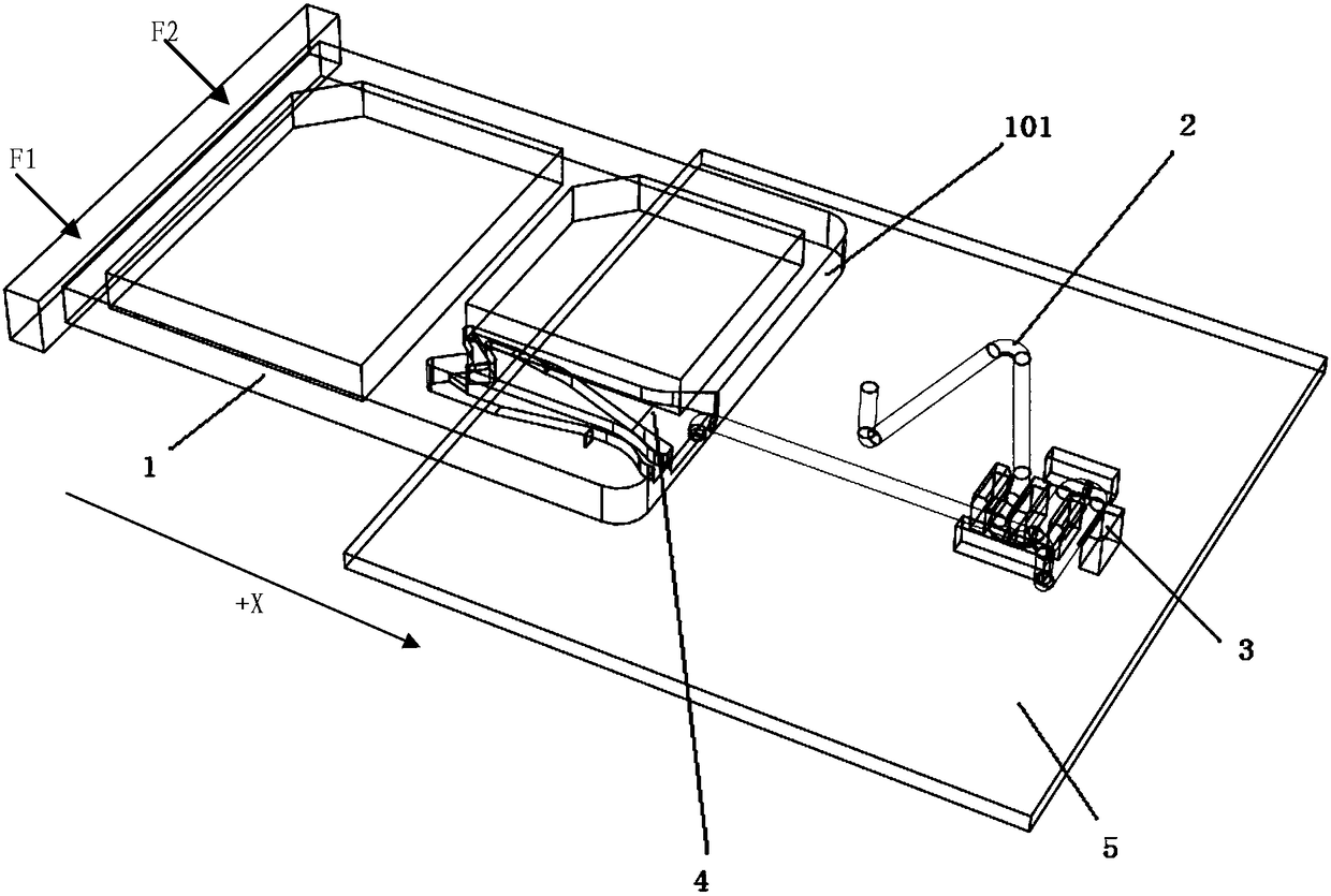
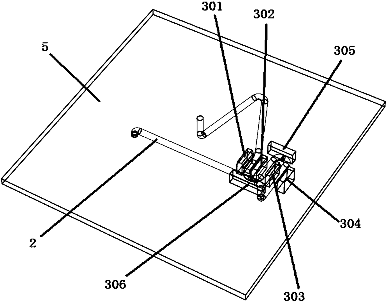
[0021] refer to figure 1 , shows a schematic structural view of a card tray loading and unloading device in an embodiment of the present invention. In this embodiment, the card tray loading and unloading device may include: a card tray 1 , a spring 2 and a limiting device 3 .
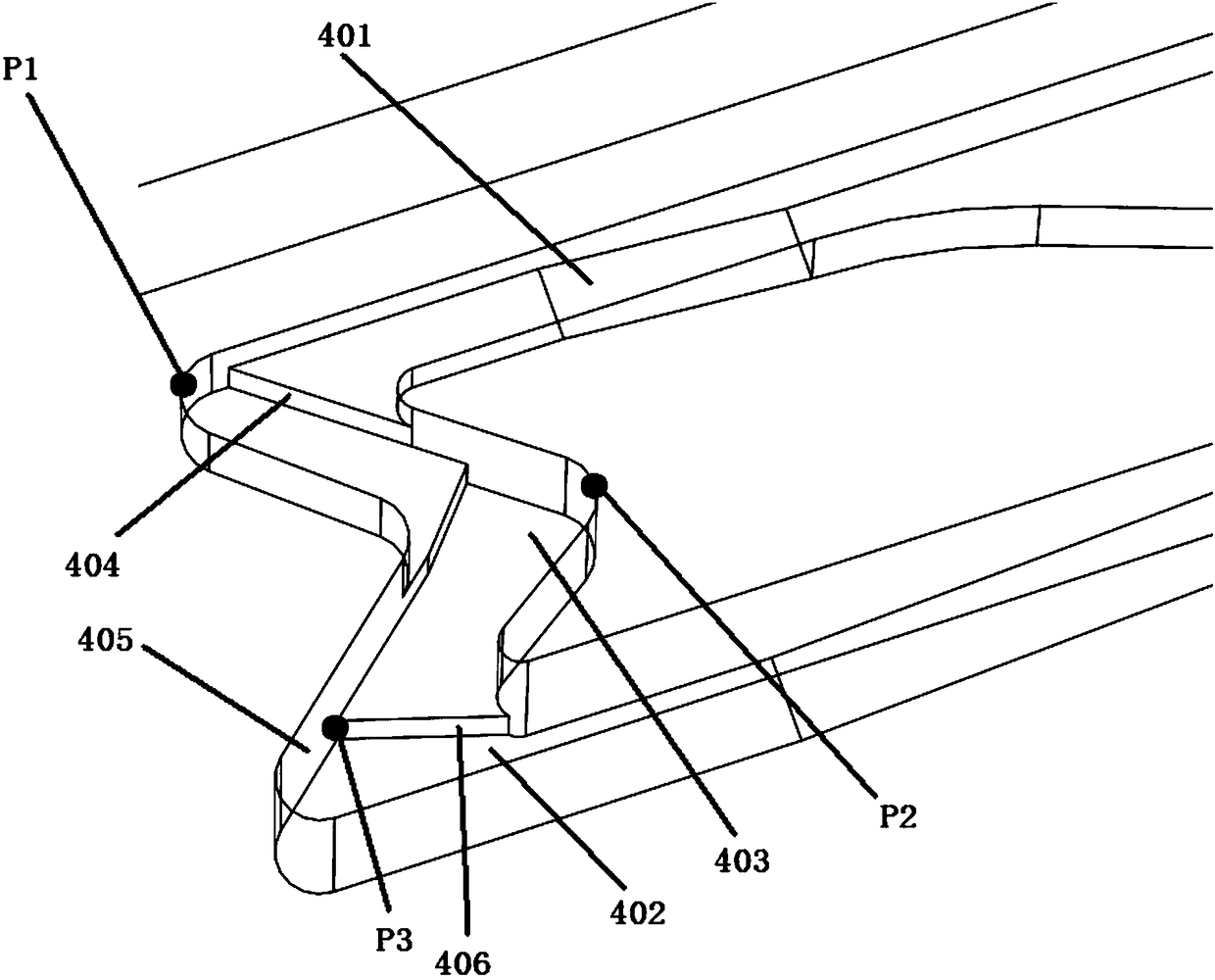
[0022] In this embodiment, the card tray 1 can be manufactured by powder metallurgy or CNC (Computerized Numerical Control Machine, computer numerical control machine tool) processing. The main difference between the card holder 1 of this embodiment and the existing card holders is that: the card holder 1 of this embodiment is provided with a special guide groove 4 , and the spring 2 can slide in one direction in the guide groove 4 . For example, during the installation and removal process of the card tray 1, the movement of the spring 2 in the guide groove 4 is unidirectional.
[0023] For ease of description, in this embodiment, see Figure 4 , the two ends of the spring 2 can be recorded as: one e...
Embodiment 2
[0032] On the basis of the first embodiment above, this embodiment further details the structure of a card tray loading and unloading device.
[0033] Such as Figure 1 to Figure 4 As shown, in this embodiment, the card tray loading and unloading device may include: a card tray 1 , a spring 2 and a limiting device 3 , and the card tray 1 is provided with a guide groove 4 .
[0034] One end 201 of the spring is connected to the card holder 1 through the guide groove 4 , and the other end 202 of the spring is spaced apart from the first side 101 of the card holder 1 near the guide groove 4 . The limiting device 3 is fixed on the terminal equipment; the limiting device 3 is connected with the spring 2 to fix the spring 2 and limit the lateral and longitudinal displacement of the spring 2 .
[0035] Preferably, in this embodiment, at the third set position of the spring 2, the limit device 3 is connected to the spring 2, so that when the spring 2 is in a free state, the extended ...
Embodiment 3
[0058] In combination with the foregoing embodiments, this embodiment takes the loading and unloading process of the card tray in the mobile terminal as an example to further describe the specific structure of the card tray loading and unloading device in detail. In this embodiment, the device for loading and unloading a card tray is applied in a mobile terminal, that is, the mobile terminal may include the device for loading and unloading a card tray in the foregoing embodiments.
[0059] Cato installation process:
[0060] combined with the above Figure 1-4 , in this embodiment, the Cato installation process may include the following steps:
[0061] Step 12, the user applies an external force F1 to the card tray 1, and the card tray 1 moves in a positive direction (such as +X direction) under the action of the external force F1, wherein one end 201 of the spring moves along the first groove 401 in the card tray 1 slide.
[0062] Step 14, when one end 201 of the spring mo...
PUM
 Abstract
Description
Claims
Application Information
 - R&D
- Intellectual Property
- Life Sciences
- Materials
- Tech Scout
- Unparalleled Data Quality
- Higher Quality Content
- 60% Fewer Hallucinations
Browse by: Latest US Patents, China's latest patents, Technical Efficacy Thesaurus, Application Domain, Technology Topic, Popular Technical Reports.
© 2025 PatSnap. All rights reserved.Legal|Privacy policy|Modern Slavery Act Transparency Statement|Sitemap|About US| Contact US: help@patsnap.com


