
Cloth clip on cloth stretching frame

A technology of stretch cloth and cloth clip, which is applied in the field of quilting machines, can solve problems such as interference and trouble, and achieve the effect of facilitating structural adjustment

Inactive Publication Date: 2020-05-29
徐政贤
View PDF0 Cites 0 Cited by
  • Summary
  • Abstract
  • Description
  • Claims
  • Application Information

AI Technical Summary

Problems solved by technology

At present, the clips on the stretcher frame are generally fixed on the frame of the stretcher frame by screws, and the position cannot be adjusted after fixing, but the frame of some stretcher frames is located to meet the needs of different sizes of bedding, and the frame size can be adjusted. When the frame size is adjusted At this time, the clips originally fixed on the frame will cause interference, and the interfering clips need to be removed, and it is troublesome to adjust the frame size of the stretcher frame

Method used


Image

  • Cloth clip on cloth stretching frame
  • Cloth clip on cloth stretching frame
  • Cloth clip on cloth stretching frame

Examples


Embodiment Construction

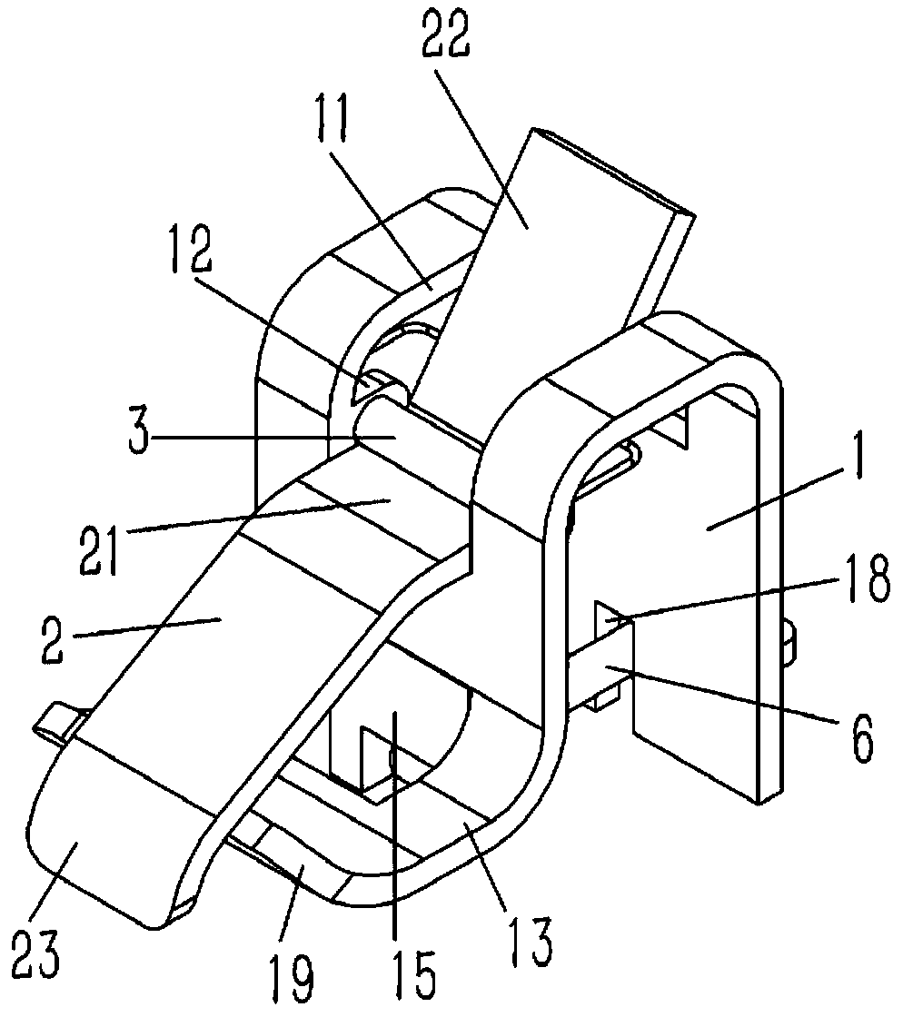
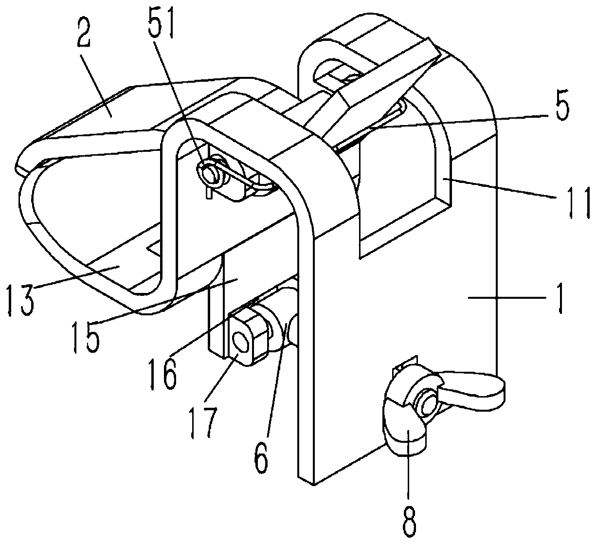
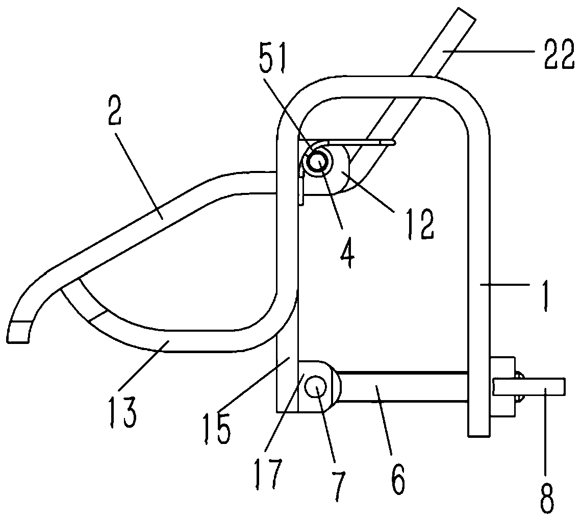
[0020] Example: see Figures 1 to 4 As shown, a cloth clip on a stretcher frame includes a "冂"-shaped support plate 1, the support plate 1 is composed of a vertical front panel, a rear panel and a horizontal top plate, and the side edge of the front end of the support plate 1 is curved A horizontal lower splint 13 is folded, and the upper end of the support plate 1 is formed with a first slot 11 that runs through the front and rear end faces of the support plate 1. The front panel of the support plate 1 on both sides of the first slot 11 is bent and formed with a rearward Extended first lug 12; the upper side of the lower splint 13 is provided with an oblique upper splint 2, the upper end of the upper splint 2 is formed with a horizontal transition plate 21, and the rear end of the transition plate 21 is formed with an oblique pressure plate 22 , the pressing plate 22 and the transition plate 21 are all inserted in the first slot 11 of the support plate 1, and the upper end of...


PUM


Abstract

The invention discloses a cloth clip on a cloth stretching frame. The cloth clip comprises a support plate shaped like an inverted U; a horizontal lower clamping plate is formed by bending the side edge of the front end of the support plate, a first slot penetrating through the front end surface and the rear end surface of the support plate is formed at the upper end of the support plate, and first support lugs extending backwards are formed by upwards bending the front panel of the support plate at the two sides of the first slot; the upper side of the lower clamping plate is provided with anobliquely arranged upper clamping plate, a horizontal transition plate is formed at the upper end of the upper clamping plate, an obliquely arranged pressing plate is formed at the rear end of the transition plate, both the pressing plate and the transition plate are inserted into the first slot of the support plate, and the upper end of the pressing plate is exposed out of the upper end surfaceof the support plate; and the transition plate is fixedly connected with a shaft sleeve, a first articulated shaft is inserted in the shaft sleeve, and the two ends of the first articulated shaft arearticulated on the first support lugs and expose the first support lugs.

Description

technical field [0001] The invention relates to the technical field of quilting machines, in particular to a cloth clip on a cloth frame. Background technique [0002] Quilting refers to stitching the outer fabric and the inner core in a straight line or in a decorative pattern. At present, the quilted fabrics are mainly made of bedding, down jackets, etc. Bedding is a common product that needs quilting. Before quilting , the perimeter of the quilt needs to be fixed on the quilted stretcher frame with clips. At present, the clips on the stretcher frame are generally fixed on the frame of the stretcher frame by screws, and the position cannot be adjusted after fixing, but the frame of some stretcher racks is located to meet the fixing of bedding of different sizes, and the frame size can be adjusted. When the frame is adjusted in size , the clips originally fixed on the frame will cause interference, it is necessary to remove the interfering clips, and it is troublesome to a...

Claims


Application Information

Patent Timeline
Patent Type & Authority Applications(China)
IPC IPC(8): D05B35/00
CPCD05B35/00
Inventor 徐政贤
Owner 徐政贤
Learn More