Large-deformation water stop device and gate valve

A water stop device and large deformation technology, applied in water conservancy projects, marine engineering, coastline protection and other directions, can solve problems such as the inability to adapt to the large deformation requirements of the gate, the separation of water stop parts, and water leakage.

Pending Publication Date: 2020-05-29
CHINA WATER RESOURCES PEARL RIVER PLANNING SURVERYING & DESIGNING
View PDF0 Cites 0 Cited by
  • Summary
  • Abstract
  • Description
  • Claims
  • Application Information

AI Technical Summary

Problems solved by technology

[0003] However, at present, the compression deformation of the water stop at the bottom of the gate is limited. If the deformation of the gate is large at the water stop, due to the small compression deformation of the water stop, the wa

Method used


Image

  • Large-deformation water stop device and gate valve
  • Large-deformation water stop device and gate valve
  • Large-deformation water stop device and gate valve

Examples


no. 1 example

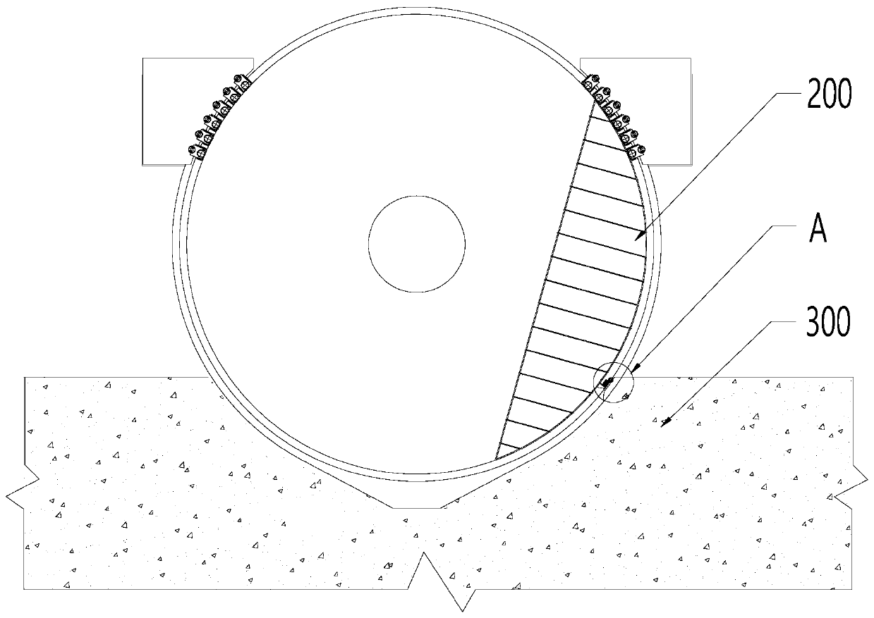
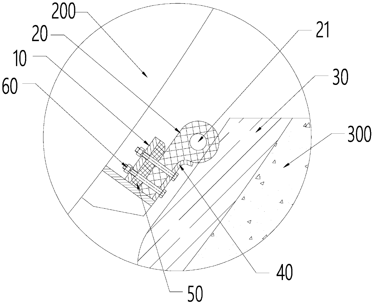
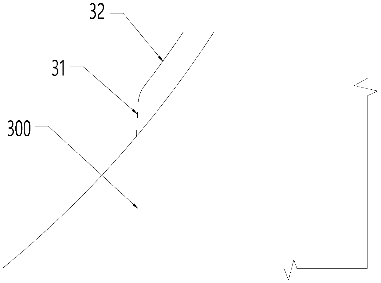
[0039] Such as Figure 1-Figure 5 As shown, this embodiment provides a large deformation water stop device, including: a bracket 10, a flexible water stop 20 and a water stop embedded part 30, the flexible water stop 20 is installed on the bracket 10, and the bracket 10 is used to connect with the gate The water-stop embedded part 30 is set relative to the gate, and the water-stop embedded part 30 is embedded in the bottom sill 300 of the gate system. There is a gap between the water-stop embedded part 30 and the gate. When the gate 200 is closed, the flexible water-stop part 20 It is located between the gate 200 and the water-stop embedded part 30 .

[0040] The flexible water stop 20 includes a first section 22 and a second section 23 connected to each other, the thickness of the first section 22 is greater than the thickness of the second section 23, the first section 22 is provided with a through hole 21 along the length direction, the first section 22 The maximum thickne...

no. 2 example

[0062] A gate system includes a gate and the large-deformation water-stop device provided in the above-mentioned first embodiment, and the bracket in the large-deformation water-stop device is connected to the gate.

[0063] Further, the gate system also includes a sill 300, which is located at the bottom of the gate, and the sill 300 includes a concrete structure layer, and the water-stop embedment 30 is pre-embedded in the concrete structure layer of the sill 300, and the water-stop embedment 30 Part of the area protrudes outside the concrete structure layer so as to be in contact with the flexible water stop 20. When the gate is in the open state, the flexible water-stop member 20 is separated from the water-stop embedded member 30; when the gate is in the closed state, part of the gate protrudes from the bottom sill 300, and the flexible water-stop member 20 is in contact with the water-stop embedded member 30 to realize the water-stop seal. water.

[0064] Furthermore, a...


PUM

PropertyMeasurementUnit
Diameteraaaaaaaaaa

Abstract

The invention provides a large-deformation water stop device and a gate valve, and relates to the technical field of the water conservancy project. The large-deformation water stop device comprises abracket, a flexible water stop part and a water stop embedded part, wherein the flexible water stop part is mounted on the bracket, and the bracket is connected to a gate; the water stop embedded partis opposite to the gate, and a gap is formed between the water stop embedded part and the gate; while the gate is in a closed state, the flexible water stop part is positioned between the gate and the water stop embedded part; the flexible water stop part comprises a first section and a second section which are connected to each other; the thickness of the first section is greater than that of the second section; a through hole is formed inside the first section in a length direction; the biggest thickness, in the radial direction of the gate, of the first section is 150mm-250mm; and the biggest distance between the flexible water stop part and the gate is greater than the smallest distance between the water stop embedded part and the gate. The large-deformation water stop device is applied to a gate system, and the water stop part in the large-deformation water stop device has relatively great compression amount, so that greater deformation of the gate can be adapted.

Description

technical field [0001] The invention relates to the technical field of water conservancy engineering, in particular to a large deformation water stop device and a gate system. Background technique [0002] In the field of water conservancy engineering, the water stop at the bottom of the rotary steel gate generally uses a water stop. The water stop is compressed and deformed between the gate and the bottom sill, so as to play the role of sealing and water stop. [0003] However, at present, the compression deformation of the water stop at the bottom of the gate is limited. If the deformation of the gate is large at the water stop, due to the small compression deformation of the water stop, the water stop will be separated from the bottom sill, resulting in water leakage. [0004] Therefore, the compression amount of the water stop member in the prior art is relatively small, and cannot meet the working requirements of large deformation of the gate. Contents of the invent...

Claims


Application Information

Patent Timeline
IPC IPC(8): E02B7/40E02B7/54
CPCE02B7/40E02B7/54
Inventor 张祖林陆伟张发茂陆海军汪艳青李勇郭建斌章光
Owner CHINA WATER RESOURCES PEARL RIVER PLANNING SURVERYING & DESIGNING
Why Eureka
Try Eureka