Multi-pole circuit breaker

A circuit breaker and multi-pole technology, applied in circuit breaker parts and other directions, can solve the problems of contact ablation, difficulty of arc extinguishing, contact burnout, etc., to avoid ablation, shorten burning time, and prolong electrical life. Effect

Active Publication Date: 2019-04-02
CHANGSHU SWITCHGEAR MFG CO LTD (FORMER CHANGSHU SWITCHGEAR PLANT)
View PDF10 Cites 1 Cited by
  • Summary
  • Abstract
  • Description
  • Claims
  • Application Information

AI Technical Summary

Problems solved by technology

[0006] Taking phase A as an example, once a three-phase short circuit occurs, the load terminal of phase A and the load terminal of phase B will be conducted, and at the same time, the dynamic and static contacts of each phase will open to form an arc. At this time, the current path is as shown in the figure, followed by phase A Incoming line terminal, static contact of phase A, grid plate of phase A, moving contact of phase A, short circuit occurrence point, moving contact of phase B, grid plate of phase B, static contact of phase B, incoming line terminal of phase B, the arc will Burn between the moving contact and the arc grid until the arc is extinguished, which will cause a large amount of ablation of the contact
[0007] During the three-phase short circuit breaking process of the circuit breaker, there will always be a current path from the moving contact to the static contact. In other words, the arc will always burn between the moving contact and the arc grid for a period of time until the arc is broken The degree of ablation of the contacts depends on the energy of the arc. The higher the energy of the arc, the more serious the burning of the contacts. Especially, in the DC circuit, since there is no zero-crossing point, the difficulty of extinguishing the arc will increase. improve

Method used


Image

  • Multi-pole circuit breaker
  • Multi-pole circuit breaker
  • Multi-pole circuit breaker

Examples


Embodiment 1

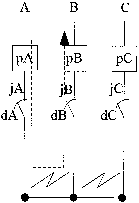
[0028] See figure 2 , figure 2 A, B, and C shown in the figure represent phase A, phase B and phase C of the multi-pole circuit breaker; figure 2 DA, dB and dC shown in the figure represent the A-phase moving contact, B-phase moving contact and C-phase moving contact of the multi-pole circuit breaker respectively; figure 2 The jA, jB and jC indicated in the figure represent the A-phase stationary contact, the B-phase stationary contact and the C-phase stationary contact of the multi-pole circuit breaker respectively; figure 2 The pA, pB and pC shown in the figure respectively represent the A-phase arc-striking grid, the B-phase arc-striking grid and the C-phase arc-striking grid of the multi-pole circuit breaker.

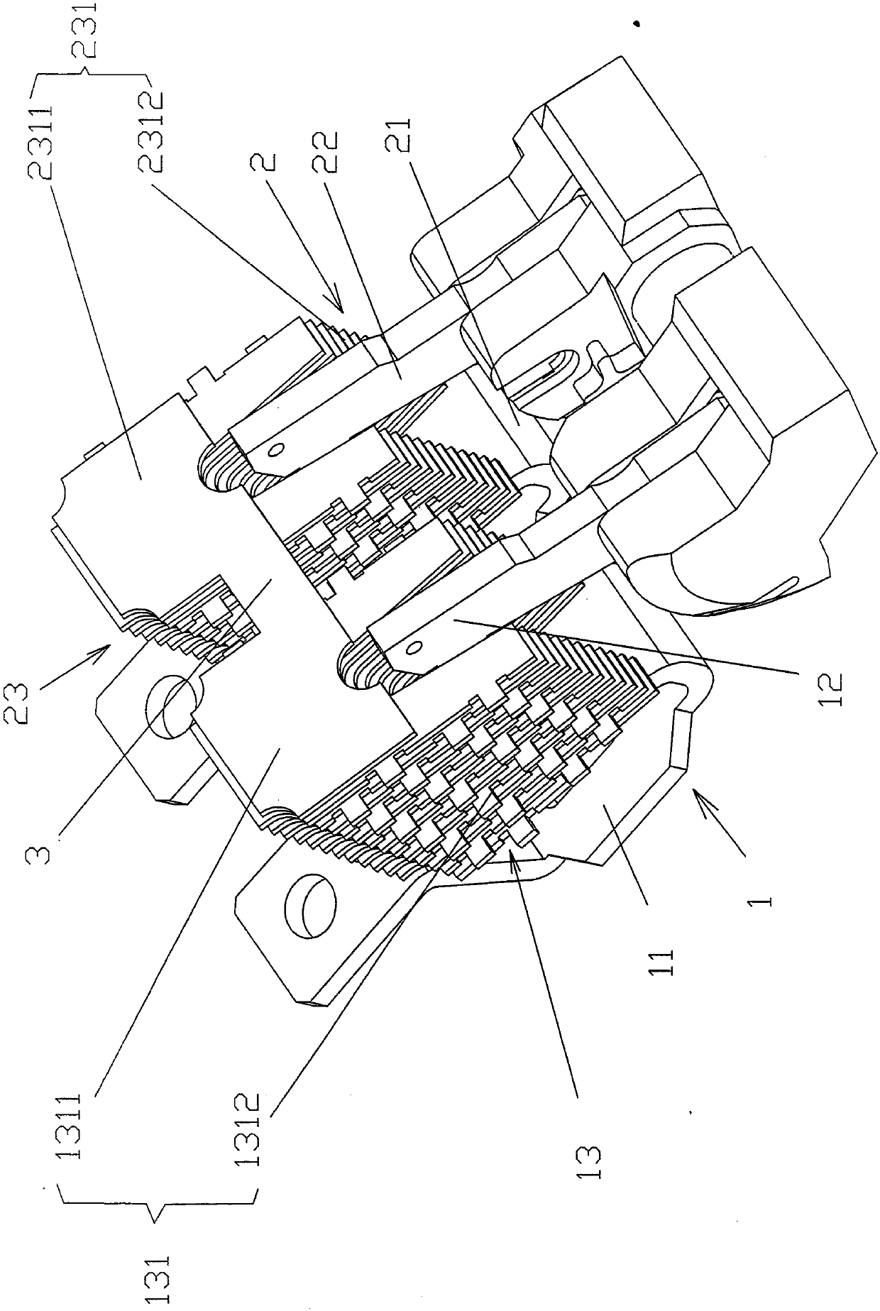
[0029] See image 3 , Shows a first pole unit 1 and a second pole unit 2, which are arranged side by side in a multi-pole circuit breaker. The first pole unit 1 includes a first static contact 11, and a first static contact 11 Contacting or separating the first mova...

Embodiment 2

[0034] See Figure 4 And combine figure 2 In this embodiment, the aforementioned equipotential connecting member 3 is formed by bending upward the edge portion of the first arcing piece 1311 toward the side of the second arcing piece 2311 and the first bending portion 31 formed by The second arcing piece 2311 faces the edge portion of one side of the first arcing piece 1311 and is formed by a second bending portion 32 that is bent upward at a position corresponding to the first bending portion 31. The first and second The two bending parts 31 and 32 are fixedly connected to each other (also called "electrical connection").

[0035] The aforementioned first bending portion 31 and the second bending portion 32 are fixedly connected by the bending portion fixing connecting member 33, specifically by screws, but they can also be fixedly connected by riveting (riveting), or even welding or The first and second bending portions 31 and 32 are fixedly connected in other equivalent ways....

Embodiment 3

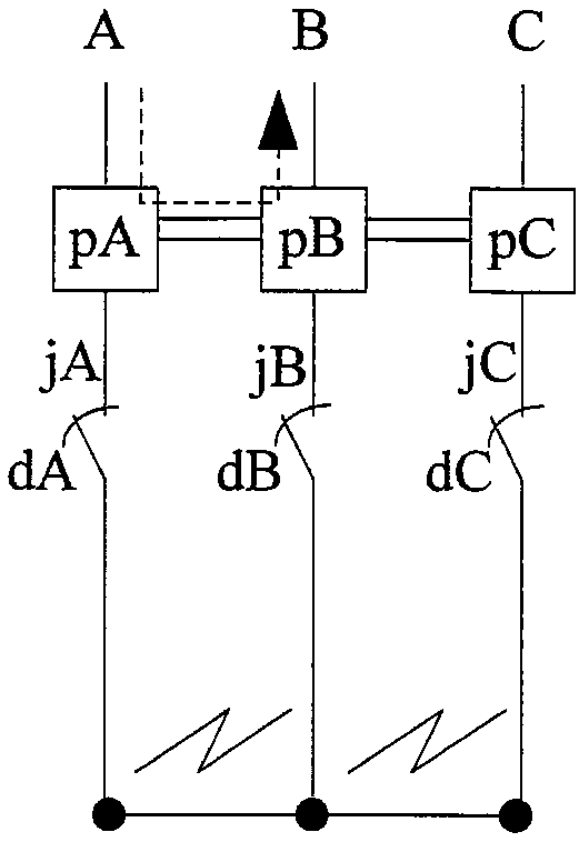
[0039] See Figure 5 with Image 6 The plurality of first grid pieces 131 include a first arc-initiating piece 1311 at the top and a plurality of first arc-extinguishing grid pieces 1312 under the first arc-inducing piece 1311. The equipotential connector 3 connects the first arc-striking piece 1311 and the second static contact 21 of the second pole unit 2. due to Figure 5 The meanings of A, B and C, dA, dB and dc, jA, jB and jC, pA, pB and pC are the same as above. figure 2 , So I won’t repeat it.

[0040] The effects of Embodiment 3 are as follows:

[0041] Such as Figure 5 As shown, the A phase is still taken as an example. Since the first arcing piece 1311 of the A phase is connected to the second static contact 21 of the B phase, after the arc on the moving contact is transferred to the arc extinguishing device, the current path no longer passes The moving contact, but from the A-phase terminal, the A-phase static contact (ie the first static contact 11) flows through it...


PUM


Abstract

A multi-pole circuit breaker includes at least one first pole unit at least one second pole unit, each first pole unit includes a first static contact, a first movable contact and a first arc extinguishing device, each first arc extinguishing device includes a plurality of first grids, the plurality of first grids are stacked in a spaced state, each second pole unit comprises a second static contact, a second movable contact and a second arc extinguishing device, each second arc extinguishing device comprises a plurality of second grids, and the plurality of second grids are stacked in a spaced state. The multi-pole circuit breaker further comprises an equipotential connection member which is connected with one in the first grids and one of the second grids or connected with one of the first grids and the second static contacts, and the first grids between the equipotential connection member and the first static contacts and / or the second grids between the equipotential connection member and the second static contacts are employed to cut and break the arc between the first static contacts and the second static contacts. The burning time of the arc on the movable contact is shortened, the breaker breaking capacity is improved, and the electric life is prolonged.

Description

Technical field [0001] The invention belongs to the technical field of low-voltage electrics, and specifically relates to a multi-pole circuit breaker. Background technique [0002] Multi-pole circuit breaker is used as a protection component of the power grid. Its function is to cut off the circuit in time when there is a short-circuit current or an overload current in the circuit to ensure that the electrical appliances in the circuit are not damaged. When the circuit breaker is opened, an arc will be generated between the moving and static contacts. Due to the large arc energy, the arc cannot stay between the moving and static contacts for a long time, otherwise it will cause severe ablation of the contacts, or even Burned out circuit breaker. [0003] How to quickly guide the arc from the contact area to the arc extinguishing grid area has become the key technology of the circuit breaker. The usual methods include setting up a magnetic arc-igniting piece near the static contac...

Claims


Application Information

Patent Timeline
IPC IPC(8): H01H73/18
CPCH01H73/18
Inventor 马俊贤刘洪武陈会林
Owner CHANGSHU SWITCHGEAR MFG CO LTD (FORMER CHANGSHU SWITCHGEAR PLANT)
Why Eureka
Try Eureka