Eureka AIR delivers breakthrough ideas for toughest innovation challenges, trusted by R&D personnel around the world.

Transverse partition plate of column and column with same

A technology for diaphragms and columns, applied in the direction of columns, pier columns, pillars, etc., can solve the problems of welding deformation of steel pipes, difficulty in ensuring the straightness of columns, etc., achieve uniform force on the whole, ensure the compactness of columns, and have a wide range of applications Effect

Pending Publication Date: 2020-05-29
SHANGHAI OPEN STEEL JOIST
View PDF0 Cites 2 Cited by
  • Summary
  • Abstract
  • Description
  • Claims
  • Application Information

AI Technical Summary

Problems solved by technology

[0003] The purpose of the present invention is to propose a column diaphragm and a column with a diaphragm, to solve the problem that the diaphragm of the traditional structural column in the background technology needs to break the steel pipe many times, and the welding deformation of the steel pipe may occur during assembly, which is difficult to solve. The problem of ensuring the straightness of the column

Method used


Image

  • Transverse partition plate of column and column with same
  • Transverse partition plate of column and column with same
  • Transverse partition plate of column and column with same

Examples


Embodiment 1

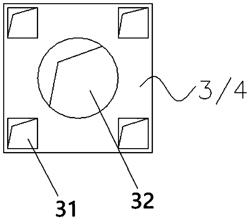
[0029] Such as figure 1 As shown, the present invention proposes a diaphragm 3 / 4 of a column, and the diaphragm 3 / 4 is preset with a through hole 32 for pouring concrete and a hole 31 for passing through a steel pipe.

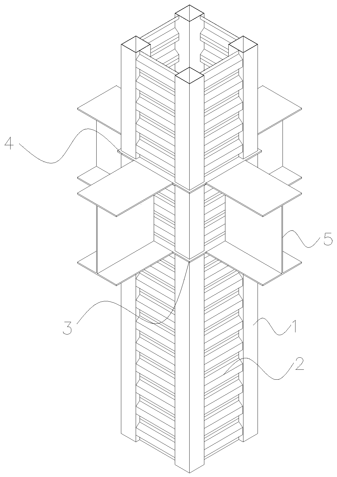
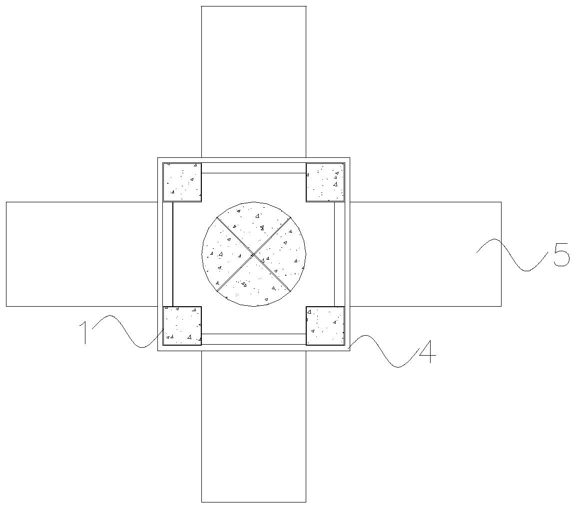
[0030] Such as figure 2 with image 3 As shown, it is a column with the above-mentioned diaphragm 3 / 4, including multiple sets of diaphragms 3 / 4 and the column body; each group of diaphragms 3 / 4 includes an upper diaphragm 4 and a lower diaphragm 3; The upper transverse diaphragm 4 and the lower transverse diaphragm 3 are arranged in parallel in relative up and down positions;

[0031] The column body includes side plates 2 and a plurality of corner steel pipes 1; a side plate 2 is connected between adjacent corner steel tubes 1 to form a column, and the corner steel tubes 1 and side plates 2 are connected by welding, which can To ensure the airtightness of the column as a whole, and in this embodiment, the side plate 2 is a corrugated web, and a flat side ...

Embodiment 2

[0043] Such as Figure 4 , Figure 5 with Image 6 As shown, the overall structure of embodiment 2 is roughly the same as that of embodiment 1, and the same parts will not be repeated here, and the difference technical features are as follows: Figure 5 with Image 6 As shown, the external beam 5 outside the column is not perpendicular to the column; therefore, the present invention adopts Figure 4 For the diaphragm 3 / 4 of other structures shown, the diaphragm 3 / 4 adopts a polygonal shape. In this embodiment, a pentagonal shape is adopted, so that one side of the diaphragm 3 / 4 is not perpendicular to the normal The external beam 5 can be smoothly lapped. According to the overlapping condition of the external beam 5 required in the actual scene, the shape of the 3 / 4 of the diaphragm can be adjusted accordingly, and the extension angle of the outer edge of the 3 / 4 of the diaphragm can be adjusted to further realize the connection between the diaphragm and the external beam....


PUM


Abstract

The invention provides a transverse partition plate of a column and the column with same. Holes for inserting steel pipes are pre-formed in the transverse partition plate, and filler through holes forpouring concrete into a middle cavity of the crust column are reserved, so that the steel pipes of the column do not need to be cut off for multiple times, the problem that the column is not straightdue to the fact that corner steel pipe welding deformation and column up-down dislocation possibly occur during assembly is avoided, meanwhile, beam-column joints form effective connection, and effective transmission of structural force is achieved.

Description

technical field [0001] The invention relates to the technical field of construction, in particular to a column diaphragm and a column with the transverse diaphragm. Background technique [0002] The column developed by Ouban is a column with square steel tubes and corrugated webs and pouring concrete in it, which is called "carapace column". At the junction of columns and beams, in order to allow the force of the beam flange to be transmitted into the interior of the column and transmitted to the adjacent beams, it is necessary to set up a "partition" inside the column. In the traditional method of clapboard, the steel pipe of the column will be cut off, and the steel pipe and the clapboard will be welded. This practice will cause the steel pipe of the column to be cut off many times, and problems of welding deformation and non-straightness may occur during assembly. Contents of the invention [0003] The purpose of the present invention is to propose a column diaphragm ...

Claims


Application Information

Patent Timeline
IPC IPC(8): E04C3/32E04C3/34
CPCE04C3/32E04C3/34
Inventor 陈明
Owner SHANGHAI OPEN STEEL JOIST
Why Eureka
Eureka Blog
Learn More