
Rocket fairing separation test device

A technology for separating test and fairing, applied in the field of spacecraft, can solve the problem of high test cost, and achieve the effect of overcoming high test cost, avoiding pressure and low cost

Active Publication Date: 2020-05-29
BEIJING XINGJI RONGYAO SPACE TECH CO LTD +1
View PDF6 Cites 1 Cited by
  • Summary
  • Abstract
  • Description
  • Claims
  • Application Information

AI Technical Summary

Problems solved by technology

[0005] Therefore, the technical problem to be solved in the present invention is to overcome the high defect of test cost of rocket fairing separation test device in the prior art, thereby providing a kind of rocket fairing separation test device

Method used


Image

  • Rocket fairing separation test device
  • Rocket fairing separation test device
  • Rocket fairing separation test device

Examples


Embodiment Construction

[0051] The technical solutions of the present invention will be clearly and completely described below in conjunction with the accompanying drawings. Apparently, the described embodiments are some of the embodiments of the present invention, but not all of them. Based on the embodiments of the present invention, all other embodiments obtained by persons of ordinary skill in the art without making creative efforts belong to the protection scope of the present invention.

[0052] In the description of the present invention, it should be noted that the terms "center", "upper", "lower", "left", "right", "vertical", "horizontal", "inner", "outer" etc. The indicated orientation or positional relationship is based on the orientation or positional relationship shown in the drawings, and is only for the convenience of describing the present invention and simplifying the description, rather than indicating or implying that the referred device or element must have a specific orientation, ...


PUM


Abstract

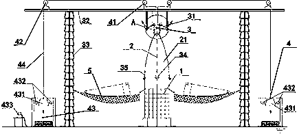
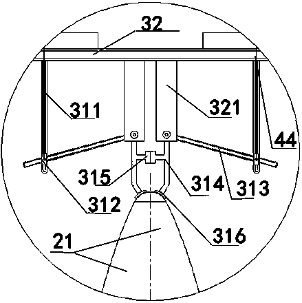
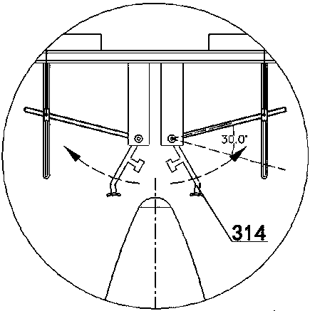
The invention provides a rocket fairing separation test device. The rocket fairing separation test device comprises a base station, a frame body and a locking mechanism, wherein the frame body is arranged above the base station; the locking mechanism is arranged on the frame body and comprises a crank assembly, a fairing body placing cavity suitable for placing a fairing body is arranged between the crank assembly and the base station, and the crank assembly is arranged on the outer side of the fairing body placing cavity; and the crank assembly has a locking position acting on the outer contour position of the fairing body placing cavity and an unlocking position leaving the outer contour position of the fairing body placing cavity under power driving. According to the rocket fairing separation test device, the locking mechanism is arranged to replace an explosive bolt in a pyrotechnic device, compared with the prior art, the device can achieve the pre-locking function without adopting a pyrotechnic connection unlocking device before the fairing is separated, and the process of controlling the separation of the fairing body can be completed; and in addition, the device can be repeatedly used for a long time, the cost is low, and the defect that the test cost of the rocket fairing separation test device in the prior art is high is overcome.

Description

technical field [0001] The invention relates to the technical field of spacecraft, in particular to a rocket fairing separation test device. Background technique [0002] The separation method of fairing can be divided into integral separation and split separation. Split-flap separation can be divided into rotary throwing separation and flat throwing separation. The fairing structure of split type separation is generally divided into two lobes or even multiple lobes along the axial direction. Before separation, the lobes are fixed by a connecting unlocking device, and then connected to the rocket body through the bottom end of the fairing. [0003] The separation surface between the two axial lobes is called the longitudinal separation surface, and the separation surface where the bottom end surface of the fairing is fixedly connected with the arrow body is called the transverse separation surface. At the beginning of the separation and spin throwing, the horizontal separa...

Claims


Application Information

Patent Timeline
Patent Type & Authority Applications(China)
IPC IPC(8): F42B35/00F42B15/36
CPCF42B15/36F42B35/00
Inventor 彭小波卢凤翎郑立伟
Owner BEIJING XINGJI RONGYAO SPACE TECH CO LTD
Learn More