
A three-dimensional measurement method for projecting non-uniform fringes in non-fully constrained systems

A constraint system, non-uniform technology, applied in measurement devices, image analysis, instruments, etc., can solve the problems of low selection accuracy, difficult binary coding, irregular distribution, etc., to suppress diffusion, improve deployment accuracy, and improve measurement. The effect of efficiency

Active Publication Date: 2019-04-23
HEBEI UNIV OF TECH
View PDF5 Cites 0 Cited by
  • Summary
  • Abstract
  • Description
  • Claims
  • Application Information

AI Technical Summary

Problems solved by technology

Due to the strong anti-interference ability of binary coded black and white stripes to various noises, the accuracy of unwrapped phase is higher. In addition, compared with other binary coded phase unraveling methods, this method only needs three auxiliary fringe images to achieve 2 6 This encoding combination shortens the measurement time while ensuring the measurement accuracy, but the binary encoding method generally has the problem of low accuracy in the selection of the auxiliary fringe binarization threshold during decoding.
In addition, the distribution of truncated phase boundaries of non-uniform fringes is irregular, making the binary coding for non-uniform fringe boundaries very difficult

Method used


Image

  • A three-dimensional measurement method for projecting non-uniform fringes in non-fully constrained systems
  • A three-dimensional measurement method for projecting non-uniform fringes in non-fully constrained systems
  • A three-dimensional measurement method for projecting non-uniform fringes in non-fully constrained systems

Examples


Embodiment Construction

[0035]The following will clearly and completely describe the technical solutions in the embodiments of the present invention. Obviously, the described embodiments are part of the embodiments of the present invention, but not all of the embodiments. Based on the embodiments of the present invention, all other embodiments obtained by persons of ordinary skill in the art without making creative efforts belong to the protection scope of the present invention.

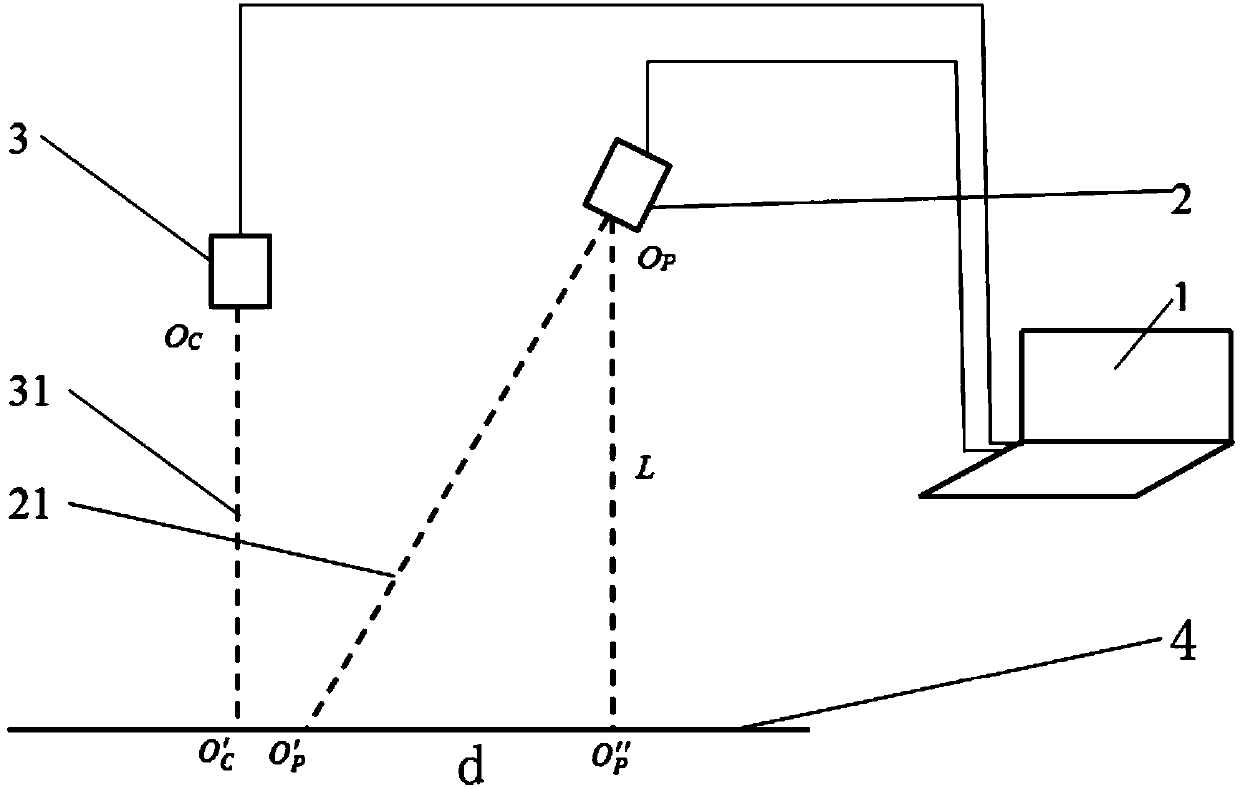
[0036] The three-dimensional measurement method of projecting non-uniform stripes in the non-completely constrained system designed by the present invention is based on the following hardware design (see figure 1 ), hardware includes computer 1, DLP projector (abbreviated projector) 2, CCD camera (abbreviated camera) 3, reference plane 4; Described projector 2 and camera 4 are connected with computer 1 control by wire respectively; Described computer 1 Including the software supporting the projector 2, the image acquisition...


PUM


Abstract

The invention discloses a three-dimensional measurement method for projecting non-uniform stripes in a non-complete constraint system. The three-dimensional measurement method uses a computer to obtain multiple phase-shift cosine striped image and auxiliary images and uses a projector to project the striped images to a reference plane, an object to be detected or planes of various heights; a camera synchronously shoots transformative striped images and the auxiliary images on the reference image, the object to be detected and the planes of various heights; a computer obtains a truncation phase of a phase shift strip and performs phase unwrapping; and then three-dimensional feature data of the object is obtained. The three-dimensional measurement method utilizes a continuous absolute phase to directly solve and obtain the height of the object, does not need to solve a phase difference, improves measurement efficiency and reduces an error introduced while solving the phase difference. The three-dimensional measurement method adopts the non-complete constraint system, has not strict requirements for installation of a measurement system, relieves a constraint that a connection line between a camera optic center and a projector optic center is parallel to the reference plane, and relieve a constraint a camera optic axis is intersected with a projector optic axis at one point on the reference plane.

Description

technical field [0001] The invention relates to the field of three-dimensional optical measurement, in particular to a three-dimensional measurement method for projecting non-uniform fringes in a non-completely constrained system. Background technique [0002] In the field of machine vision, the three-dimensional structured light measurement method has been widely used in reverse engineering, cultural relics protection, medicine and other fields due to its non-contact measurement, fast speed, and high precision. Among them, the four-step phase-shift surface structured light measurement method, due to A measurement can obtain more data and has been widely studied. In the traditional surface structured light measurement technology, a system model with strict constraints on the installation position of the camera and projector is usually used, and the measurement form of vertical shooting and oblique projection is adopted. [0003] At present, the commonly used measurement syst...

Claims


Application Information

Patent Timeline
Patent Type & Authority Patents(China)
IPC IPC(8): G01B11/06G06T7/55
CPCG01B11/0608
Inventor 戴士杰冀红彬张慧博宋涛吕海东
Owner HEBEI UNIV OF TECH
Learn More