
Reciprocator-type quick-releasing mechanism

a quick-release mechanism and receiver-type technology, applied in mechanical devices, casings/cabinets/drawers, casings/cabinets/drawers details, etc., can solve the problems of short serviceable period, easy breakage of the engaging structure of the conventional detachable keyswitch, and lower loading capacity

Active Publication Date: 2020-02-18
WISTRON CORP
View PDF7 Cites 1 Cited by
  • Summary
  • Abstract
  • Description
  • Claims
  • Application Information

AI Technical Summary

Benefits of technology

[0003]The present disclosure provides a reciprocator-type quick-releasing mechanism of conveniently assembling a first module with a second module for solving above drawbacks.
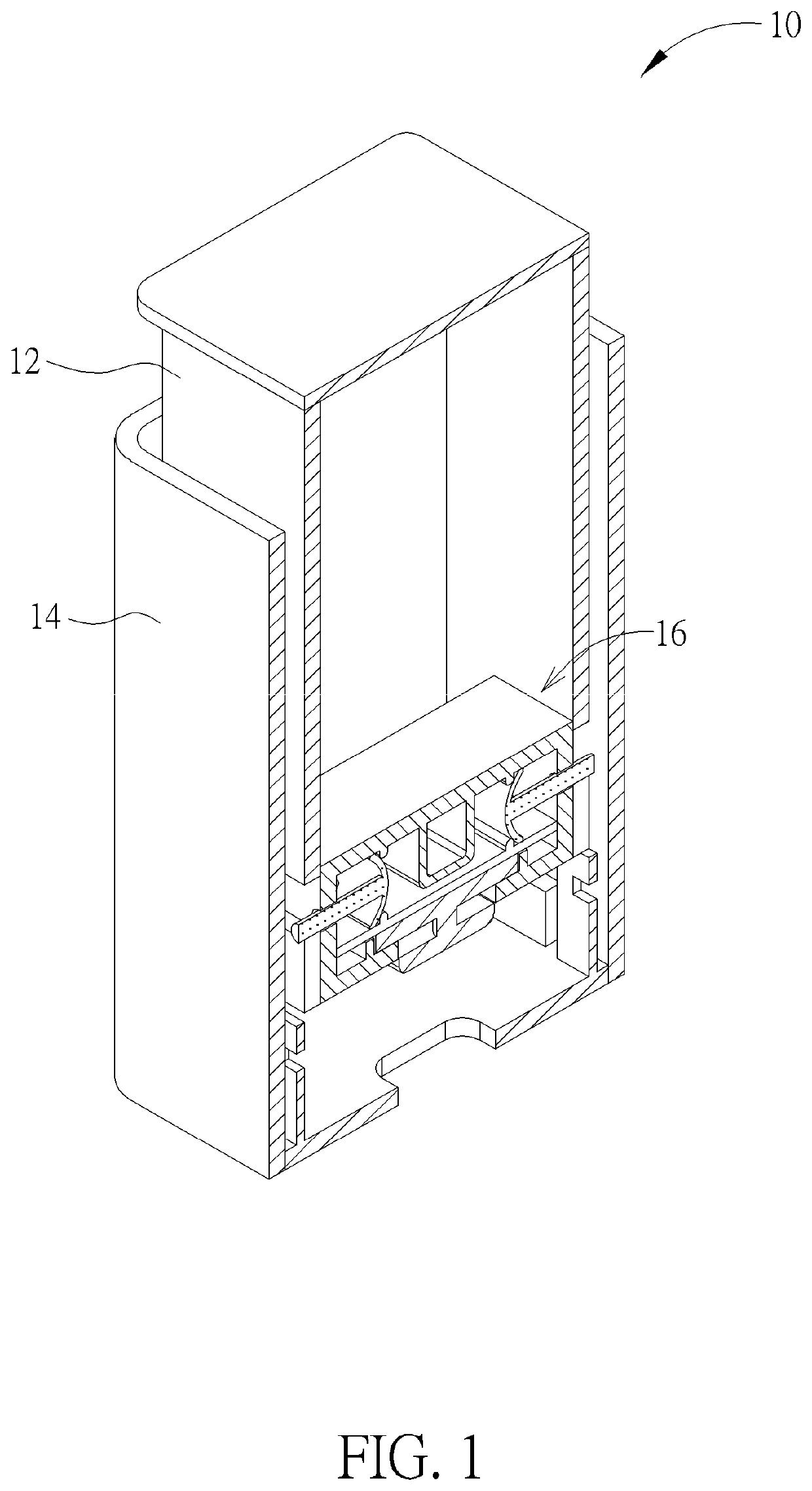
[0026]The user can press the reciprocator-type quick-releasing mechanism exposed from the outer surface of the second module to release constraint of a relative movement between the first module and the second module. The reciprocator-type quick-releasing mechanism can be arbitrarily disposed on a bottom surface or a lateral surface of the second module, which depends on user's demand. The present disclosure provides several embodiments of the reciprocator-type quick-releasing mechanism, the reciprocator-type quick-releasing mechanism can be activated by the pressing or pulling manner, and the reciprocator-type quick-releasing mechanism has an automatic recovering function for rapidly assembly and disassembly of the first module and the second module.

Problems solved by technology

For disassembly of the conventional detachable keyswitch, the engaging structure is pulled open by high pressure to separate the keyswitch and the casing, therefore the engaging structure of the conventional detachable keyswitch is easily broken due to violent force or is easily abraded and deformed in accordance with stress concentration, and has a drawback of short serviceable period.
Another conventional double-click push latch utilizes a hook movably inside a track to lock the push latch on the casing, and has drawbacks of lower loading capability because of being made by small-size plastic material and limited range of application.

Method used


Image

  • Reciprocator-type quick-releasing mechanism
  • Reciprocator-type quick-releasing mechanism
  • Reciprocator-type quick-releasing mechanism

Examples


first embodiment

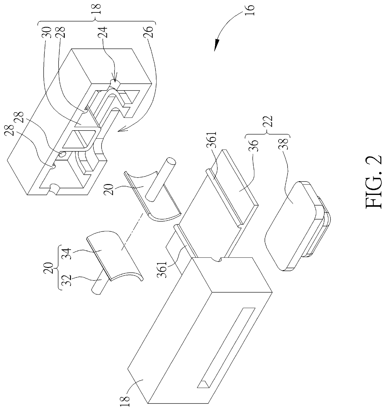
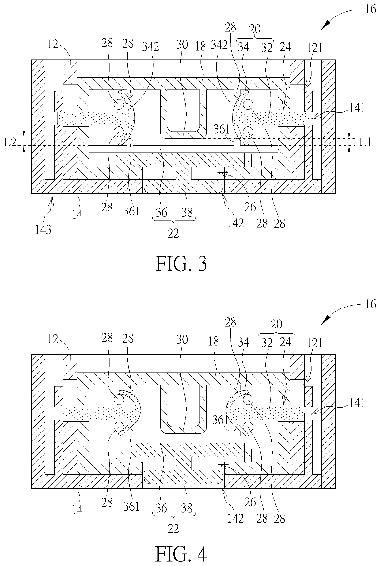
[0043]In the first embodiment, the resilient portion 34 is an arc structure. Two opposite ends of the resilient portion 34 respectively contact against the base 18 and the pushing portion 36 via the engaging portion 28 and the engaging striped block 361, and the constraining portion 32 is connected to a middle region of the resilient portion 34. As shown in FIG. 3, the reciprocator-type quick-releasing mechanism 16 is set in an initial mode, the actuating portion 38 aligns with the second opening 142, and a bending angle of the resilient portion 34 is utilized to maintain the constraining portion 32 kept at a mode passing through the second piercing hole 141 for structural interference; meanwhile, the first module 12 cannot be disassembled from the second module 14. As shown in FIG. 4, the actuating portion 38 is pressed to move into the second opening 142, the resilient portion 34 is flexibly deformed by pressure of the pushing portion 36, the constraining portion 32 is moved deepl...

third embodiment

[0047]In the third embodiment, the resilient portion 34″ is the arc structure. The two opposite ends of the resilient portion 34″ are engaged with the engaging portions 28 of the base 18, and the pushing portion 36 of the actuating component 22 presses the middle region of the resilient portion 34″ in a separable manner. In addition, the pushing portion 36 and the actuating portion 38 of the actuating component 22 are connected with each other, and the pushing portion 36 aligns with the first opening 26 and the second opening 142 for being an operation interface. As shown in FIG. 9, the reciprocator-type quick-releasing mechanism 50 is set in an initial mode, the constraining portion 32 is located inside the first piercing hole 24 (or inside the first piercing hole 24 and the aperture 121), the buckling portion 52 is buckled with the aperture 121, and the first module 12 cannot be disassembled from the second module 14. As shown in FIG. 10, the actuating portion 38 is pressed into t...


PUM


Abstract

A reciprocator-type quick-releasing mechanism includes a base, a latching component and an actuating component. The base is disposed inside a first module, and has a first piercing hole and a first opening. The latching component is disposed on the base, and includes a constraining portion and a resilient portion. The constraining portion aligns with the first piercing hole and a second piercing hole on a second module. The resilient portion is connected to the constraining portion. The actuating component is slidably disposed on the base and includes a pushing portion and an actuating portion. The actuating portion is connected to the pushing portion and protrudes from the first opening and a second opening on the second module. The actuating portion moves relative to the second opening to flexibly deform the resilient portion via the pushing portion, so as to remove the constraining portion from the second piercing hole.

Description

BACKGROUND OF THE INVENTION1. Field of the Invention[0001]The present disclosure relates to a quick-releasing mechanism, and more particularly, to a reciprocator-type quick-releasing mechanism of conveniently assembling a first module with a second module.2. Description of the Prior Art[0002]A conventional detachable keyswitch is moved at a single operation direction, and an engaging structure of the conventional detachable keyswitch is directly installed inside a hole formed on a casing. For disassembly of the conventional detachable keyswitch, the engaging structure is pulled open by high pressure to separate the keyswitch and the casing, therefore the engaging structure of the conventional detachable keyswitch is easily broken due to violent force or is easily abraded and deformed in accordance with stress concentration, and has a drawback of short serviceable period. Another conventional double-click push latch utilizes a hook movably inside a track to lock the push latch on the...

Claims


Application Information

Patent Timeline
Patent Type & Authority Patents(United States)
IPC IPC(8): H05K5/02F16B21/10
CPCH05K5/0221F16B21/10Y10T403/591H01H13/02H05K5/0013H05K7/1489
Inventor WU, KU-CHOU
Owner WISTRON CORP
Learn More