
Unmanned aerial vehicle detection positioning system and method

A positioning system and UAV technology, applied in the field of detection and positioning, can solve the problems of small reflection area of ​​micro and small UAVs and reduced detection and positioning accuracy of UAVs, and achieve the effect of improving detection and positioning accuracy and high estimation accuracy

Active Publication Date: 2020-05-29
XIAN UNIV OF TECH
View PDF7 Cites 0 Cited by
  • Summary
  • Abstract
  • Description
  • Claims
  • Application Information

AI Technical Summary

Problems solved by technology

[0004] However, the passive detection system can detect and locate the UAV only when there is a signal from the external radiation source, and the reflection area of ​​the micro UAV is small, which will reduce the detection and positioning accuracy of the UAV

Method used


Image

  • Unmanned aerial vehicle detection positioning system and method
  • Unmanned aerial vehicle detection positioning system and method
  • Unmanned aerial vehicle detection positioning system and method

Examples


Embodiment Construction

[0053] In order to make the purpose, technical solutions and advantages of the embodiments of the present invention clearer, the technical solutions in the embodiments of the present invention will be clearly and completely described below in conjunction with the drawings in the embodiments of the present invention. Obviously, the described embodiments It is a part of embodiments of the present invention, but not all embodiments.

[0054] Accordingly, the following detailed description of the embodiments of the invention provided in the accompanying drawings is not intended to limit the scope of the claimed invention, but merely represents selected embodiments of the invention. Based on the embodiments of the present invention, all other embodiments obtained by persons of ordinary skill in the art without creative efforts fall within the protection scope of the present invention.

[0055] It should be noted that like numerals and letters denote similar items in the following f...


PUM


Abstract

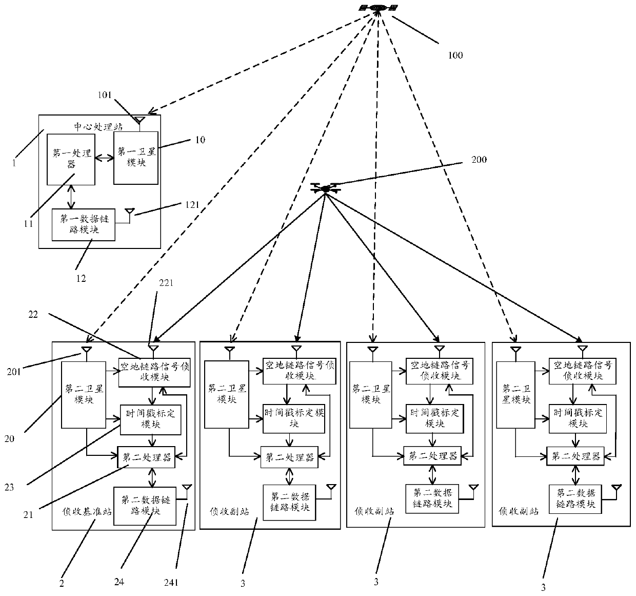
The invention provides a detection positioning system and method of an unmanned aerial vehicle and relates to the technical field of detection positioning. The system comprises a central processing station and a plurality of monitoring stations, wherein the central processing station comprises a first satellite module, a first processor, a first satellite antenna and a first data link module, thefirst satellite module and the first data link module are respectively connected with the first processor, each monitoring station comprises a second satellite module, a second processor, a second satellite antenna, an air-ground link signal interception module, an interception antenna, a timestamp calibration module and a second data link module, the air-ground link signal interception module isrespectively connected with the interception antenna and the timestamp calibration module, and the second satellite module, the air-ground link signal interception module, the timestamp calibration module and the second data link module are respectively connected with the second processor. The system is advantaged in that detection and positioning precision of the unmanned aerial vehicle can be improved.

Description

technical field [0001] The invention relates to the technical field of detection and positioning, in particular to a detection and positioning system and method for an unmanned aerial vehicle. Background technique [0002] With the advancement of science and technology, micro-UAVs have been widely used in fields such as aerial photography, remote monitoring, and aircraft model hobbies. In recent years, incidents such as micro-UAVs intruding into the airspace of government departments, national air defense airspace, and civil / military airport clearance areas have occurred many times, resulting in serious safety hazards. Therefore, solving the detection and positioning of micro-UAVs has been achieved. received widespread attention. [0003] At present, the UAV positioning system mainly includes an active radar system and a passive detection system. The passive detection system uses the reflection or scattering of the external radiation source signal to detect and locate the U...

Claims


Application Information

Patent Timeline
Patent Type & Authority Applications(China)
IPC IPC(8): G01S19/37G01S19/42
CPCG01S19/37G01S19/42
Inventor 刘高辉贺鼎
Owner XIAN UNIV OF TECH
Learn More