A safe road corner mirror based on the principle of electromagnetic induction

An electromagnetic induction, safe technology

Active Publication Date: 2021-11-05
新疆丝路六合电气科技有限公司
View PDF5 Cites 0 Cited by
  • Summary
  • Abstract
  • Description
  • Claims
  • Application Information

AI Technical Summary

Problems solved by technology

[0005] The purpose of the present invention is to provide a safe road corner mirror based on the principle of electromagnetic induction with high safety performance for the problem of low safety of most of the traditional corner mirrors mentioned above.

Method used


Image

  • A safe road corner mirror based on the principle of electromagnetic induction
  • A safe road corner mirror based on the principle of electromagnetic induction
  • A safe road corner mirror based on the principle of electromagnetic induction

Examples


Embodiment 1

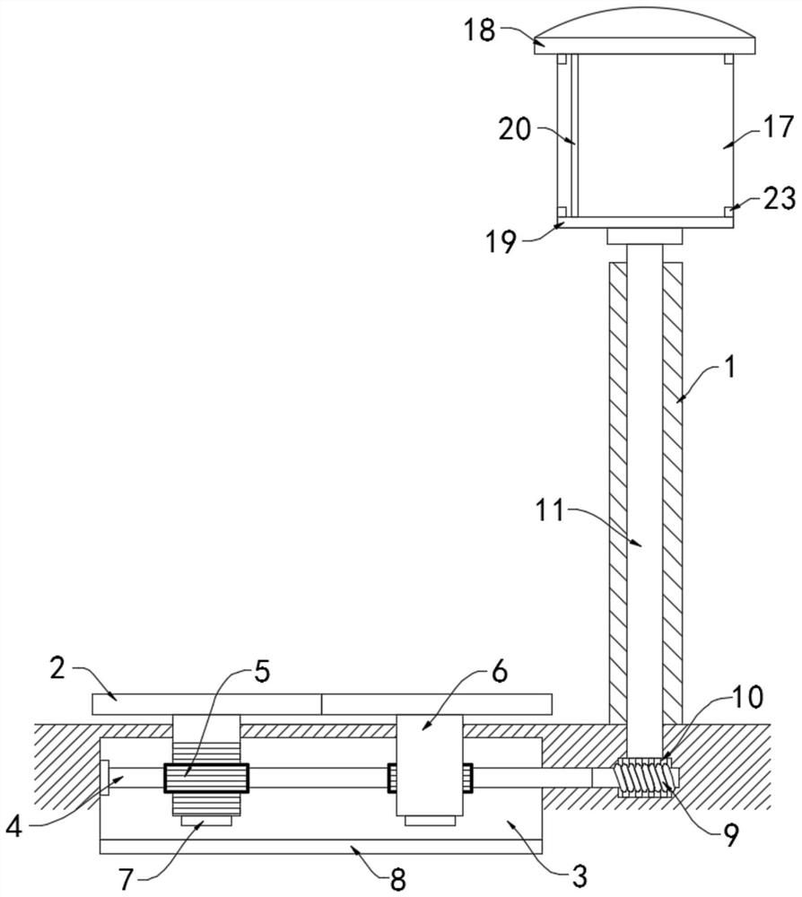
[0026] Such as Figure 1-3 As shown, a safe road corner mirror based on the principle of electromagnetic induction includes a pole 1, which is fixedly connected to the roadside at the corner of the road, and one side of the pole 1 is provided with two speed brakes 2 arranged side by side. , the two speed brakes 2 are respectively arranged above the left and right traffic lanes, vehicles on different traffic lanes will crush the speed brakes 2 at different positions, the lower ends of the two speed brakes 2 are provided with a speed reduction chamber 3, and the speed reduction chamber 3 is rotationally connected with The rotating shaft 4 arranged horizontally is rotatably connected with the side wall of the deceleration chamber 3 through a bearing.

[0027] Two gear columns 5 are fixedly sleeved on the rotating shaft 4, and a vertical rack 6 is fixedly connected to the lower side walls of the two speed brakes 2. The bars 6 and the gear columns 5 are meshed and connected one by...

Embodiment 2

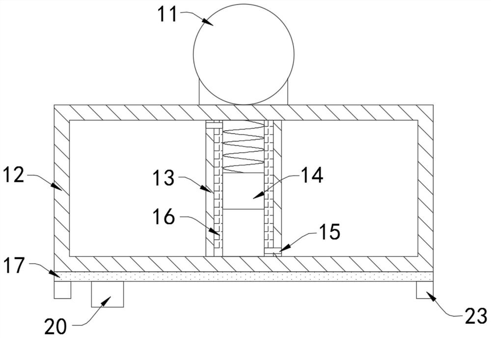
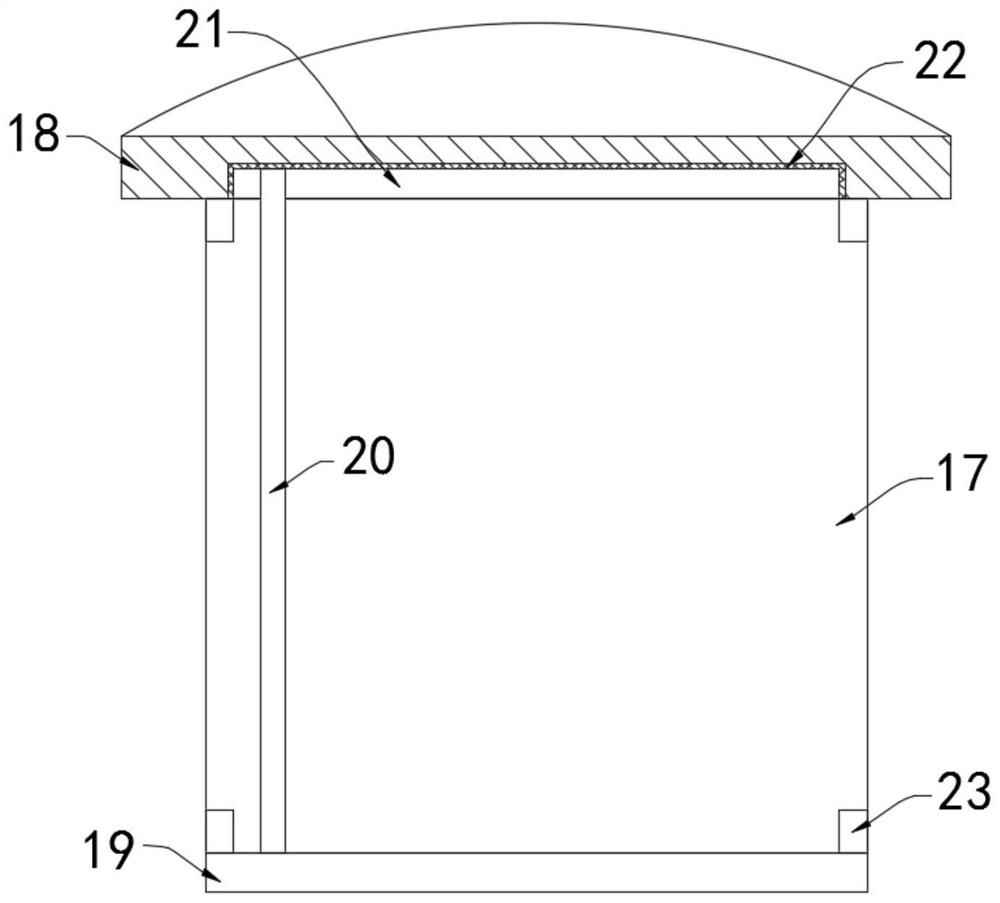
[0039] Such as Figure 4-5 As shown, the difference between the present embodiment and Embodiment 1 is: the left and right sides of the plane mirror 17 are all provided with air blowing pipes 24, and the communication hole 15 on the side wall of the driving tube 13 away from the plane mirror 17 is fixedly communicated with the air blowing pipe 24 Conductive conduit 25 .

[0040] In this embodiment, after the automobile leaves the corner, the rubber block 14 in the drive tube 13 will move in the opposite direction under the elastic action of the spring to reset, so that the air in the drive tube 13 will be sprayed to the On the static cleaning strip 20, the dust on the cleaning strip 20 is blown away.


PUM


Abstract

The invention belongs to the field of road safety, and in particular relates to a safe road corner mirror based on the principle of electromagnetic induction, which includes a pole, and one side of the pole is provided with two speed brakes arranged side by side, and the two speed brakes A deceleration chamber is provided at the lower end of the deceleration chamber, and a horizontally arranged rotating shaft is rotatably connected to the decelerating chamber. Two gear columns are fixedly sleeved on the rotating shaft, and the lower side walls of the two deceleration plates are fixedly connected with Vertically arranged racks, the lower ends of the racks extend into the deceleration chamber, and the racks are meshed with the gear columns one by one. The lower ends of each rack are fixedly connected with permanent magnets. The deceleration chamber A magnetic plate repelling the same polarity as the permanent magnet is fixedly connected to the lower side wall of the utility model. The invention makes the vehicle roll over the deceleration plate when the vehicle travels to the corner road section. At this time, the permanent magnet at the lower end of the rack fixedly connected with the deceleration plate repels the magnetic plate, which will cause obvious bumpy feeling to the driver, prompting the driver to reduce the speed of the vehicle, thereby increasing the speed of the vehicle. road safety.

Description

technical field [0001] The invention belongs to the field of road safety, in particular to a safe road corner mirror based on the principle of electromagnetic induction. Background technique [0002] In order to ensure traffic safety, various road safety reminder devices are usually installed on traffic roads, including road corner mirrors, through which the vehicles on the opposite side of the curve can be detected early to reduce the occurrence of traffic accidents. [0003] Most of the traditional road corner mirrors are set at the corners of the road, and they are all made of convex mirrors. The traffic conditions on the two roads are reflected in the corner mirrors by using the characteristics of the wide viewing range of the convex mirrors. However, the convex mirrors The image presented will be deformed to varying degrees, and it is difficult for the driver to quickly and accurately judge the road conditions of the other party, which is less safe. Moreover, a large am...

Claims


Application Information

Patent Timeline
Patent Type & Authority Patents(China)
IPC IPC(8): E01F9/619E01F9/65E01F9/529
CPCE01F9/529E01F9/619E01F9/65
Inventor 王斌朱宗一
Owner 新疆丝路六合电气科技有限公司
Why Eureka
Try Eureka