
Detector module, detector and CT equipment

A technology of detectors and sub-modules, applied to radiological diagnostic instruments, medical science, computerized tomography scanners, etc., can solve the problems of high cost and high difficulty in manufacturing CT equipment, and reduce manufacturing difficulty, cost, and data Effects for easy correction and optimized image quality

Pending Publication Date: 2020-06-05
NEUSOFT MEDICAL SYST CO LTD
View PDF6 Cites 1 Cited by
  • Summary
  • Abstract
  • Description
  • Claims
  • Application Information

AI Technical Summary

Problems solved by technology

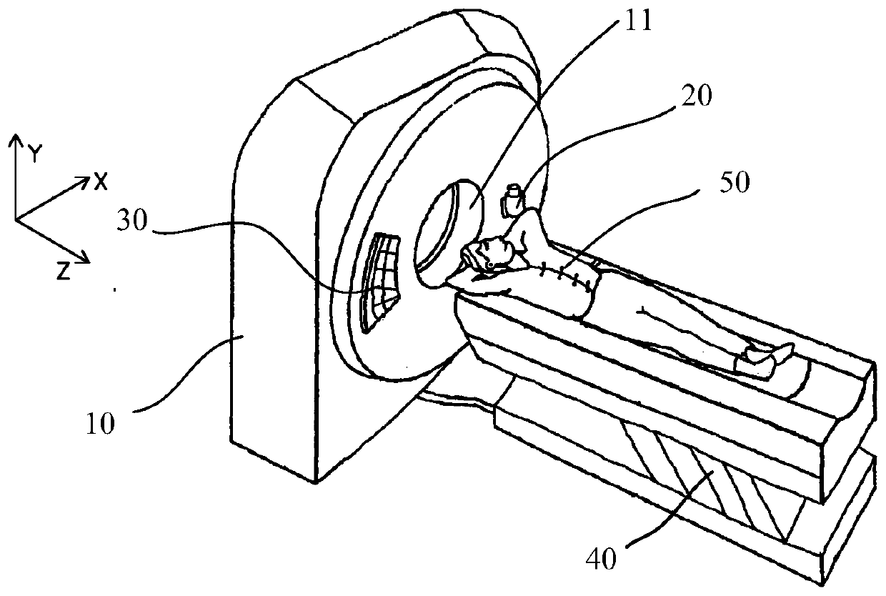
[0002] With the development of CT (Computed Tomography, electronic computer tomography) technology, the coverage of a single scan of the human body is required to be larger and larger. Correspondingly, the number of detector layers is increasing, and more and more detectors need to be installed on the housing. At the same time as the detector sub-module, the irradiation area of ​​the X-ray source as the detector signal source is also required to be larger and larger. In this way, an X-ray source with a larger target angle has to be used to achieve a large Z-direction of the CT rotation system. Imaging coverage, however, ultimately makes CT equipment with large coverage in the Z direction difficult and expensive to manufacture

Method used


Image

  • Detector module, detector and CT equipment
  • Detector module, detector and CT equipment
  • Detector module, detector and CT equipment

Examples


Embodiment Construction

[0044] Reference will now be made in detail to the exemplary embodiments, examples of which are illustrated in the accompanying drawings. When the following description refers to the accompanying drawings, the same numerals in different drawings refer to the same or similar elements unless otherwise indicated. Embodiments described in the following exemplary embodiments do not represent all embodiments consistent with the present application. Rather, they are merely examples of apparatuses and methods consistent with aspects of the present application as recited in the appended claims.

[0045] The terminology used in this application is for the purpose of describing particular embodiments only, and is not intended to limit the application. As used in this application and the appended claims, the singular forms "a", "the", and "the" are intended to include the plural forms as well, unless the context clearly dictates otherwise.

[0046] It should be understood that "first", ...


PUM


Abstract

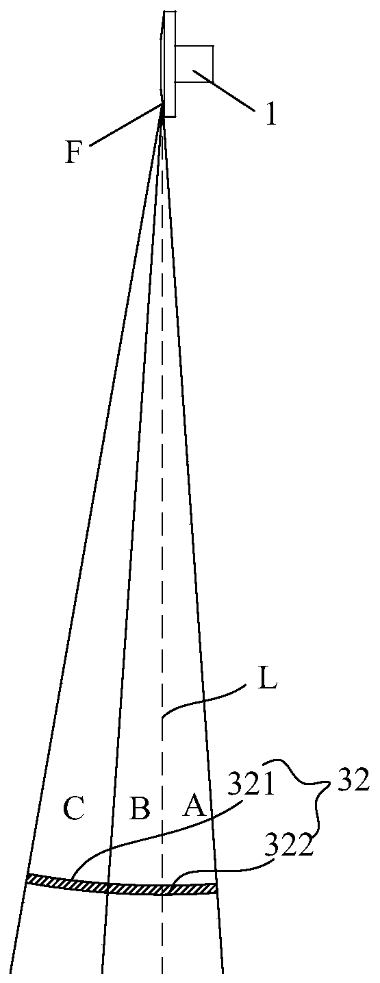
The application discloses a detector module, a detector and CT equipment. The detector module is used for detecting a ray which is emitted from an X-ray source of a CT host machine and is subjected toattenuation by a scanning object. The detector module comprises a bracket and a plurality of detector submodules mounted on the bracket, wherein each detector submodule comprises a top surface for receiving rays; the top surfaces of the detector submodules are arrayed in an arc shape or in a straight line along the Z direction of a CT rotary system; the top surfaces of the detector submodules form a receiving region corresponding to an illumination region of the X-ray source in the YZ plane of the CT rotary system; the receiving region is asymmetric relative to a focus reference surface of the X-ray source; and the focus reference surface penetrates through the focus center of the X-ray source and is parallel to an XY plane of the CT rotary system. Through the adoption of the detector module disclosed by the invention, performance parameter requirements to the X-ray source, and manufacturing cost and difficulty of Z-direction large-coverage area (such as 512-layer ) CT equipment can be reduced.

Description

technical field [0001] The present application relates to the technical field of computed tomography, in particular to a detector module, a detector and CT equipment. Background technique [0002] With the development of CT (Computed Tomography, electronic computer tomography) technology, the coverage of a single scan of the human body is required to be larger and larger. Correspondingly, the number of detector layers is increasing, and more and more detectors need to be installed on the housing. At the same time as the detector sub-module, the irradiation area of ​​the X-ray source as the detector signal source is also required to be larger and larger. In this way, an X-ray source with a larger target angle has to be used to achieve a large Z-direction of the CT rotation system. Imaging coverage, however, ultimately makes CT equipment with large coverage in the Z direction difficult and expensive to manufacture. Contents of the invention [0003] In order to overcome som...

Claims


Application Information

Patent Timeline
Patent Type & Authority Applications(China)
IPC IPC(8): A61B6/00A61B6/03
CPCA61B6/4208A61B6/4266A61B6/035
Inventor 李双学楼珊珊于军王凤晨
Owner NEUSOFT MEDICAL SYST CO LTD
Learn More