Detector module, detector and CT equipment

A detector and sub-module technology, applied in the field of detectors, CT equipment, and detector modules, can solve the problems of increased manufacturing difficulty and high cost of detector modules, and achieve the requirements of lowering performance parameters, lowering manufacturing difficulty, and lowering manufacturing costs. Effect

Pending Publication Date: 2020-06-05
NEUSOFT MEDICAL SYST CO LTD
View PDF8 Cites 2 Cited by
  • Summary
  • Abstract
  • Description
  • Claims
  • Application Information

AI Technical Summary

Problems solved by technology

Multiple detector sub-modules installed on the housing of the detector are important components for photoelectric conversion. In order to ensure the diagnostic effect, it is necessary to install more detector sub-modules on the housing, which will cause the detector module The manufacturing difficulty is increased and the cost is high

Method used


Image

  • Detector module, detector and CT equipment
  • Detector module, detector and CT equipment
  • Detector module, detector and CT equipment

Examples


Embodiment approach

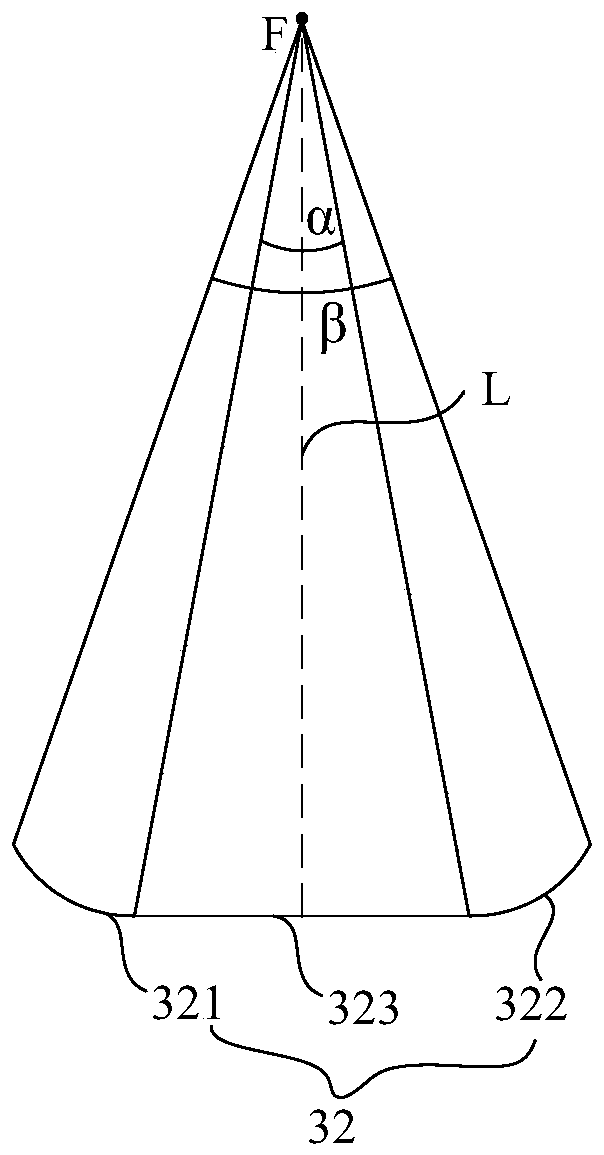
[0061] Further describe the implementation manner in which the above-mentioned trend of decreasing from the focus reference plane L to the direction away from the focus reference plane L (the edge of the detector submodule) is as follows:

[0062] refer to Figure 5 to Figure 14 , the focus reference plane L is marked, and the width of the top surface of the detector submodule close to the focus reference plane in the X direction is greater than the width of the top surface of the detector submodule away from the focus reference plane in the X direction so that each The width of the top surface of the detector sub-module in the X direction shows a decreasing trend from the focus reference plane along the Z direction away from the focus reference plane, including the following two situations:

[0063] 1. The width of the top surface of the detector sub-module close to the focus reference plane L in the X direction is greater than the width of the top surface of the detector sub...


PUM


Abstract

The invention discloses a detector module, a detector and CT equipment. The detector module is used for detecting rays which are emitted by an X-ray source of a CT host and attenuated by a scanning object, and comprises a support and a plurality of detector sub-modules arranged on the support, wherein the plurality of detector sub-modules include middle detector sub-modules located within the range of a first preset distance of a focus reference plane and edge detector sub-modules located beyond the range of the first preset distance; the focus reference plane penetrates through the focus center of the X-ray source and is parallel to an XY plane of a CT rotating system; each of the detector sub-modules includes a top surface that receives the rays; the top surfaces of the edge detector sub-modules are arranged in an arc shape in the Z direction of the CT rotating system; and the top surfaces of the middle detector sub-modules are linearly arranged along the Z direction. According to such a scheme, the manufacturing difficulty and the manufacturing cost of the detector module are reduced, and a CT detector with a large coverage range in the Z direction can be realized.

Description

technical field [0001] The present application relates to the technical field of computed tomography, in particular to a detector module, a detector and CT equipment. Background technique [0002] With the continuous development of medical level, more and more medical devices are used to assist medical diagnosis or treatment. For example, CT (Computed Tomography, computerized tomography) equipment is used to detect human diseases. CT equipment detects X-rays passing through the human body through detectors and converts the received light signals into electrical signals. Multiple detector sub-modules installed on the housing of the detector are important components for photoelectric conversion. In order to ensure the diagnostic effect, it is necessary to install more detector sub-modules on the housing, which will cause the detector module The difficulty of manufacture increases, and the cost is high. Contents of the invention [0003] In order to overcome some or all of...

Claims


Application Information

Patent Timeline
Patent Type & Authority Applications(China)
IPC IPC(8): A61B6/00A61B6/03
CPCA61B6/4208A61B6/4266A61B6/035
Inventor 楼珊珊李双学王凤晨
Owner NEUSOFT MEDICAL SYST CO LTD
Why Eureka
Try Eureka