Novel high-power high-voltage pulse power supply circuit

A high-voltage pulse power supply and high-power technology, which is applied in the field of new high-power high-voltage pulse power supply circuits, can solve the problems of difficult drive synchronization, difficult procurement, and large output impedance of full-bridge rectifier circuits, so as to reduce performance parameter requirements and facilitate popularization and application. , the effect of reducing production costs

Active Publication Date: 2013-09-04
ZHONGSHAN HAOYUAN ELECTRICAL APPLIANCE EQUIP CO LTD
View PDF4 Cites 11 Cited by
  • Summary
  • Abstract
  • Description
  • Claims
  • Application Information

AI Technical Summary

Problems solved by technology

[0004] 1. Fast recovery diodes with high voltage and high current are currently expensive in China and difficult to purchase
It is also inappropriate to separate multiple channels of rectification and then connect them in series, because the insulation voltage of most tube packages can only be AC2500V and below, and after multiple channels are separated, drive synchronization is a major difficulty, and the high voltage points on the rectifier circuit are distributed. open, making the insulation work difficult and leaving hidden dangers in the long-term use in the future
[0005] 2. High-voltage and high-power chopper devices are currently difficult to purchase at home and abroad and are expensive, and many indicators such as high-voltage and high-current devices are not ideal for shutdown speed and tailing current.
[0006] 3. For capacitive loads, the theoretical output impedance of the full-bridge rectifier circuit in the dead time is infinite, so the falling edge of the output pulse waveform will have varying degrees of tailing depending on the capacitive load

Method used


Image

  • Novel high-power high-voltage pulse power supply circuit
  • Novel high-power high-voltage pulse power supply circuit
  • Novel high-power high-voltage pulse power supply circuit

Examples


Embodiment Construction

[0029] The features of the present invention and other related features will be further described in detail below in conjunction with the accompanying drawings through embodiments, so as to facilitate the understanding of those skilled in the art:

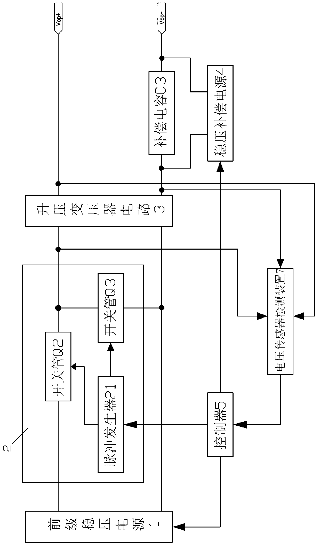
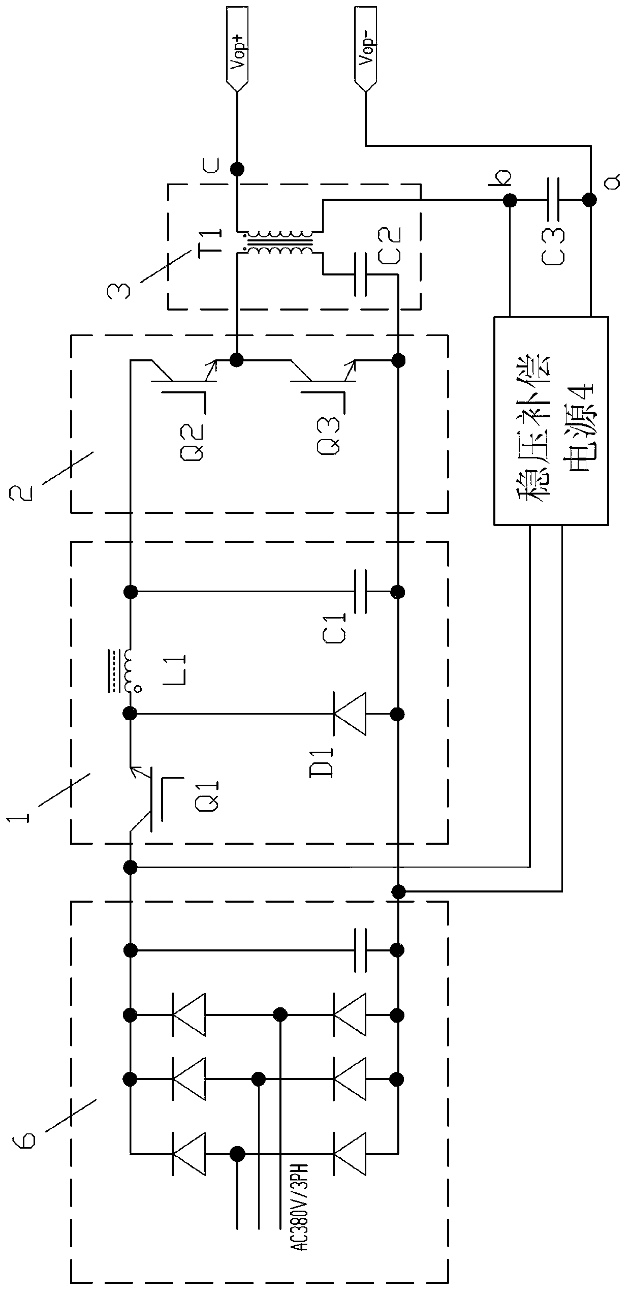
[0030] Such as Figure 1-2 As shown, a new high-power high-voltage pulse power supply circuit includes a pre-stage regulated power supply 1 connected in sequence to provide a preliminary stable DC voltage, and is used to control the pulse control of the pulsating DC voltage output by the pre-stage regulated power supply 1 Circuit 2, and a step-up transformer circuit 3 for outputting asymmetrical positive and negative square waves after boosting the input pulsating DC voltage, the pulse control circuit 2 includes a device connected in series with an input end of the step-up transformer circuit 3 The switch tube Q2 used to control the voltage input of the pre-stage pre-stabilization circuit 1, the switch tube Q3 connected in parallel...


PUM


Abstract

The invention discloses a novel high-power high-voltage pulse power supply circuit. The novel high-power high-voltage pulse power supply circuit is characterized in that a controller, a preceding stage voltage-stabilized power supply, a pulse control circuit and a boosting transformer circuit are included, wherein the preceding stage voltage-stabilized power supply, the pulse control circuit and the boosting transformer circuit are sequentially connected. The output end of the boosting transformer circuit is connected with a compensation capacitor C3 in series, and two ends of the compensation capacitor C3 are connected with voltage-stabilized compensation power supplies in parallel. A switching tube Q2, a switching tube Q3 on the pulse control circuit and a boosting transformer T1 form an asymmetric half-bridge circuit, the boosting transformer T1 outputs asymmetric positive and negative square waves which have the same period as needed high-power high-voltage narrow pulses under the control of a controller, enables the voltage-stabilized compensation power supplies connected at the two ends of the compensation capacitor C3 in parallel to conduct voltage compensation, and eventually outputs the needed high-power high-voltage narrow pulses.

Description

[technical field] [0001] The invention relates to a novel high-power high-voltage pulse power supply circuit. [Background technique] [0002] High-power pulsed magnetron sputtering technology has attracted extensive attention in the international vacuum field in recent years because of its high metal ionization rate. This technology uses high peak power and low pulse duty cycle to produce high sputtering metal Ionization, due to the short pulse time, its average power is not high, the cathode will not increase the cooling requirements of the target due to overheating, its peak power is 100 times that of ordinary sputtering, as high as 1000-3000W / c㎡; there is also the application of this The technology directly generates diamond-like film layers on the metal surface, etc., and the key equipment to realize this technology is a high-power pulse power supply. [0003] For high-power and high-voltage narrow pulse output circuits, the traditional circuit topology is driven by a f...

Claims


Application Information

Patent Timeline
Patent Type & Authority Applications(China)
IPC IPC(8): H02M9/06
Inventor 梁兆光程岐生
Owner ZHONGSHAN HAOYUAN ELECTRICAL APPLIANCE EQUIP CO LTD
Why Eureka
Try Eureka