Electromagnetic invisible sleeve structure for inner wall surface of air inlet channel

A technology for the air inlet and the inner wall surface, which is applied in the field of electromagnetic stealth sleeve structure on the inner wall of the air inlet, can solve the problems of difficulty, easy peeling and maintenance of the electromagnetic stealth coating, and achieve the reduction of the cavity effect, good electromagnetic stealth characteristics, Apply a wide range of effects

Active Publication Date: 2020-06-05
NANJING UNIV OF AERONAUTICS & ASTRONAUTICS
View PDF5 Cites 5 Cited by
  • Summary
  • Abstract
  • Description
  • Claims
  • Application Information

AI Technical Summary

Problems solved by technology

[0006] Purpose of the invention: The present invention provides a new type of electromagnetic stealth sleeve structure on the inner wall of the air inlet to solve the problems of the inner cavity effect of the air inlet based on the stealth design and the problems that the electromagnetic stealth coating is easy to fall off and difficult to maintain

Method used


Image

  • Electromagnetic invisible sleeve structure for inner wall surface of air inlet channel
  • Electromagnetic invisible sleeve structure for inner wall surface of air inlet channel
  • Electromagnetic invisible sleeve structure for inner wall surface of air inlet channel

Examples


Embodiment Construction

[0027] The present invention will be further explained below in conjunction with the drawings.

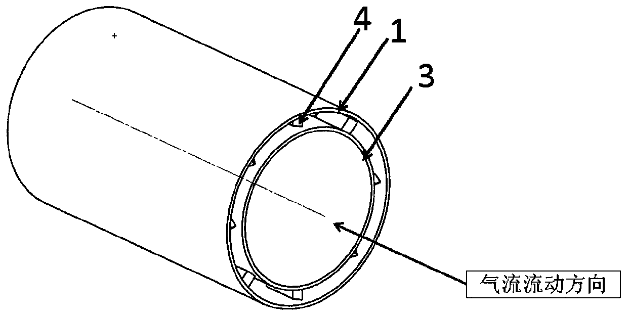
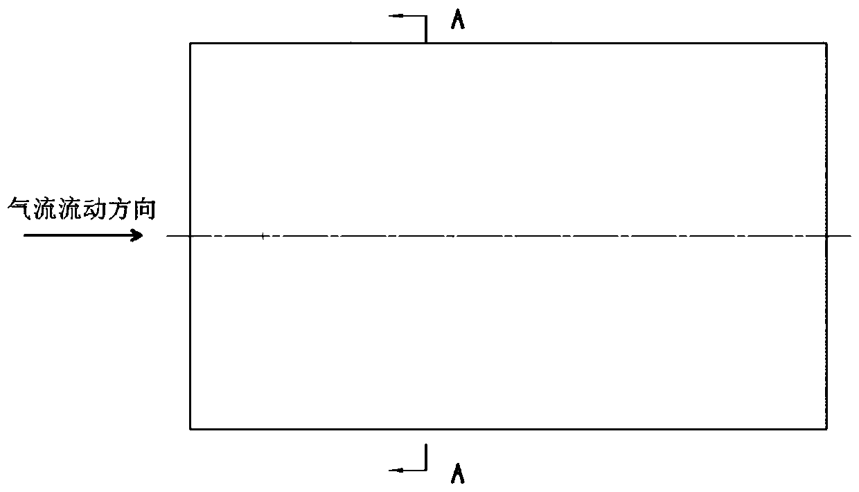
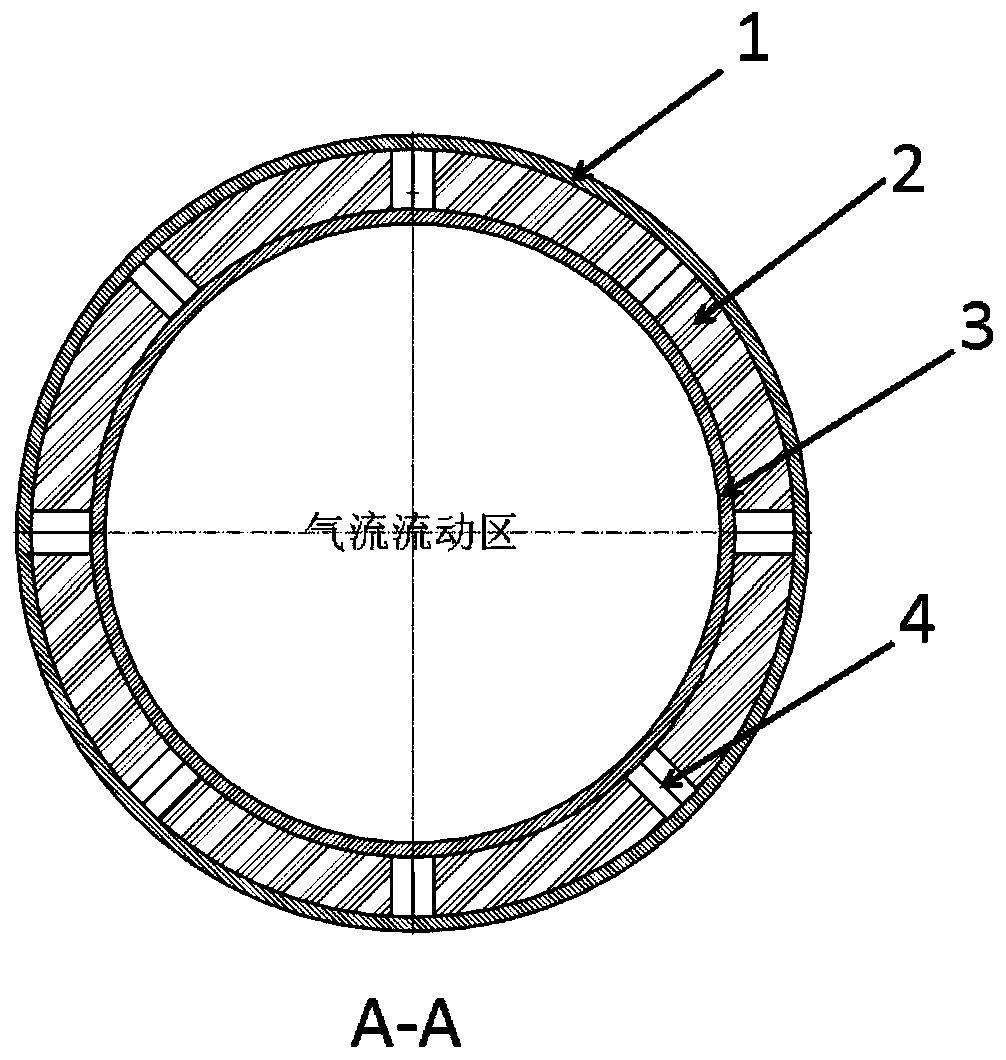
[0028] Such as Figure 1-2 An electromagnetic stealth sleeve structure on the inner wall of an air inlet is shown. The sleeve structure is arranged inside the air inlet, and the inner wall 3 of the wave-transmitting material and the main structure 1 of the air inlet are sequentially arranged radially outward. Such as image 3 As shown, there is a gap between the inner wall surface 3 of the wave-permeable material and the main structure 1 of the air inlet. A number of stiffener support members 4 are arranged inside the gap, which are respectively fixed on the inner wall surface 3 of the wave-permeable material and the main structure 1 of the air inlet. , Used to ensure the structural strength of the sleeve. The reinforcing rib supporting member 4 is prismatic, and the cross section is an elongated hexagon, such as Figure 4-6 Shown. The stiffener support members 4 are arranged in an ...


PUM


Abstract

The invention discloses an electromagnetic invisible sleeve structure for the inner wall surface of an air inlet channel. The electromagnetic invisible sleeve structure comprises a wave-transparent material inner wall surface and an air inlet channel main body structure which are sequentially arranged outwards in the radial direction, a gap is reserved between the inner wall surface of the wave-transmitting material and the air inlet channel main body structure, and a plurality of reinforcing rib supporting parts are arranged in the gap, are respectively fixed on the inner wall surface of thewave-transmitting material and the air inlet channel main body structure and are used for ensuring the structural strength of the sleeve; other positions in the gap are filled with wave-absorbing filling material layers; the wave-absorbing filling material layer comprises a wave-absorbing coating and a PMI foam layer; the wave-absorbing coating is respectively coated on the inner wall surface of the air inlet channel main body structure and the surface of the reinforcing rib supporting part; according to the sleeve structure provided by the invention, the cavity effect of the air inlet channelduring radar wave irradiation can be effectively reduced, and the problems that a stealth coating in the air inlet channel pipeline is easy to fall off and difficult to maintain can be prevented, sothat the optimal electromagnetic stealth performance is obtained under the condition that the aerodynamic performance of the air inlet channel is not changed.

Description

Technical field [0001] The invention relates to the technical field of air inlet stealth design, and mainly relates to an electromagnetic stealth sleeve structure on the inner wall of an air inlet. Background technique [0002] With the advancement of modern radar technology, the design of aircraft requires not only excellent aerodynamic characteristics, but also excellent stealth performance. The stealth performance of the aircraft is directly related to the survival of the aircraft on the battlefield, so stealth has become an aircraft. A measure of [0003] For most of the current prevention and control systems, the detection method used is radar. The radar cross section (RCS) is usually used to measure the stealth performance of aircraft. Therefore, reducing the radar cross section is very important in the stealth design of aircraft. Small radar cross section It means that the target has low detectability and high battlefield survival rate. [0004] For aircraft with air-breathi...

Claims


Application Information

Patent Timeline
Patent Type & Authority Applications(China)
IPC IPC(8): B64D33/02C09D5/30C09D5/32
CPCB64D33/02C09D5/30C09D5/32
Inventor 苏纬仪侯强
Owner NANJING UNIV OF AERONAUTICS & ASTRONAUTICS
Why Eureka
Try Eureka