Harness wire take-off device of automatic drafting machine

A technology for automatic threading and heddle threading, applied in the field of harness threading machines, can solve the problems of inconvenient separation of healds, inconvenient maintenance of hook rods, inconvenience in disassembly and assembly of hook rods, etc.

Pending Publication Date: 2020-06-05
江苏大邦智能科技有限公司
View PDF0 Cites 3 Cited by
  • Summary
  • Abstract
  • Description
  • Claims
  • Application Information

AI Technical Summary

Problems solved by technology

[0003] There are certain defects in the currently used heald pull-out device, lacking a convenient sliding mechanism for the support rod, which makes it inconvenient to separate the heald from the i

Method used


Image

  • Harness wire take-off device of automatic drafting machine
  • Harness wire take-off device of automatic drafting machine
  • Harness wire take-off device of automatic drafting machine

Examples


Embodiment Construction

[0024] In order to make the objectives, features, and advantages of the present invention more obvious and understandable, the technical solutions in the embodiments of the present invention will be described clearly and completely in conjunction with the accompanying drawings in the embodiments of the present invention. Obviously, the following The described embodiments are only a part of the embodiments of the present invention, rather than all the embodiments. Based on the embodiments of the present invention, all other embodiments obtained by those of ordinary skill in the art without creative work shall fall within the protection scope of the present invention.

[0025] The technical solutions of the present invention will be further described below in conjunction with the drawings and specific implementations.

[0026] In the description of the present invention, it should be understood that the directions or positional relationships indicated by the terms "upper", "lower", "...


PUM


Abstract

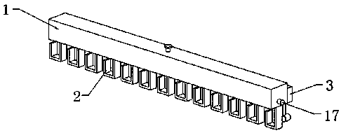
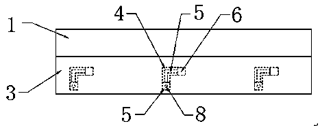
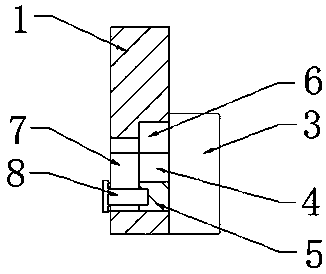
The invention discloses a harness wire take-off device of an automatic drafting machine. The harness wire take-off device comprises a transverse rod, hook-shaped rods, a supporting rod, L-shaped grooves, sliding blocks, sliding blocks, through grooves, fastening bolts, a connecting rod, an upper arc plate, a lower arc plate, mounting grooves, first springs, a T-shaped rod, a second spring, a clamping block and a round rod. The supporting rod moves upwards to drive the sliding blocks to move upwards along the L-shaped grooves, the supporting rod moves upwards to drive the connecting rod to moveso as to drive the upper arc plate and the lower arc plate to move upwards, the transverse rod is horizontally pushed to move to drive the sliding blocks to move to be attached to magnetic blocks inan adsorbed mode, the transverse rod moves to drive the upper arc plate and the lower arc plate to drive harness wires to move, the harness wires are moved to the outer sides of the hook-shaped rods,the round rod is inserted into a round hole, the hook-shaped rods are installed on the annular side face of the round rod, when a clamping groove in the round rod is aligned with a groove, the T-shaped rod moves to drive the clamping block to move to be separated from a magnetic ring, the T-shaped rod moves to drive the clamping block to move into the clamping groove, and then the position of theround rod is fixed.

Description

Technical field [0001] The invention relates to a heddle pull-out device, in particular to a heddle pull-out device of an automatic draw-in machine, belonging to the technical field of draw-in machines. Background technique [0002] One of the accessories of the loom, made of thread, steel wire or steel sheet. There is a small hole (heddle eye) in the middle for the warp to pass through. Each heddle controls one warp. When weaving, it drives the warp to move up and down to form a shuttle Mouth. It is convenient to introduce weft yarn. [0003] The currently used heddle pull-out device has certain defects. It lacks the convenient sliding mechanism of the support rod, which makes it inconvenient to detach the heald from the hook rod. At the same time, it lacks a convenient installation mechanism for the hook rod, which makes it inconvenient to disassemble the hook rod. , And it is inconvenient to maintain the hook rod. Therefore, in view of the above problems, a heddle pull-out dev...

Claims


Application Information

Patent Timeline
IPC IPC(8): D03J1/14
CPCD03J1/14
Inventor 谢中民
Owner 江苏大邦智能科技有限公司
Why Eureka
Try Eureka