Positioning pin lock for piston valve pit tool

A valve pit and positioning pin technology, which is applied in the field of fixtures and fixtures, can solve the problems of positioning pins and workpieces being separated, and achieve the effects of ensuring production tasks, stabilizing product quality, and simple structural methods

Inactive Publication Date: 2018-12-07
DONGFENG PISTON & BEARING
View PDF0 Cites 2 Cited by
  • Summary
  • Abstract
  • Description
  • Claims
  • Application Information

AI Technical Summary

Problems solved by technology

[0004] The invention provides a positioning pin lock used on the tooling of the piston valve pit, which solves the problem that the positioning pin is separated from the workpiece

Method used


Image

  • Positioning pin lock for piston valve pit tool

Examples


Embodiment Construction

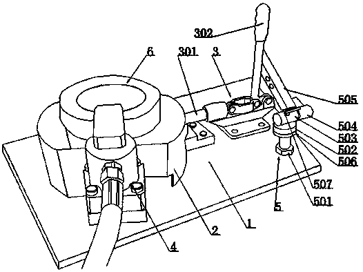
[0010] like figure 1 As shown, a positioning pin lock for piston valve pit tooling, including a tooling base plate 1, a piston stop seat 2, a clamp 3, a compression cylinder 4, a positioning pin lock 5, and a piston 6 is positioned on the piston stop seat 2, the piston pin hole is arranged on the peripheral surface of the piston stop seat 2, and the positioning pin at the front end of the clamp 3 extends into the piston pin hole to radially position the piston 6, press The tightening cylinder 4 can axially compress the piston 6, and the positioning pin lock 5 can lock the handle of the clamp 3; , short shaft 504, lock bar 505, the upright supporting column 501 can be fixed on the tooling base plate 1, the upper end of the rotating shaft seat 502 is connected with the supporting column 51; that is, the supporting column is a bolt, the rotating shaft seat is a cap nut, and the head end of the bolt Fixed on the bottom plate of the tooling fixture, the cap nut is connected with t...


PUM


Abstract

The invention relates to a positioning pin lock for a piston valve pit tool. The positioning pin lock comprises a tool bottom plate, wherein a piston stopper tire seat, a clamp, a compressing cylinderand a positioning pin lock body are arranged on the tool bottom plate, and a piston is positioned on the piston stopper tire seat; a positioning pin at the front end of the clamp extends into a piston pin hole to radially position the piston, and the compressing cylinder can axially compress the piston; the positioning pin lock body can lock a handle of the clamp; the positioning pin lock body iscomposed of a supporting column, a rotating shaft seat, a long shaft, a short shaft and a lock rod; an internal threaded hole is formed in one end of the long shaft, an external thread is arranged onthe outer circumference surface of one end of the short shaft, and an internal thread of the long shaft meshes with the external thread of the short shaft to form a movable shaft; and the short shaftcan drive the rotation and axial displacement of the lock rod, and the lock rod converts the pre-tightening force of the short shaft into the pressing force required for the positioning pin, and thatis to say, the problem of separation of the positioning pin and a workpiece is solved.

Description

technical field [0001] The invention relates to a tooling fixture for processing piston milling valve pits, in particular to a positioning pin anti-off lock applied to the tooling fixture. Background technique [0002] In the engine, in order to prevent the top of the piston from colliding with the valve, several pits are processed on the top of the piston according to the shape and position of the valve, which are usually called valve pits in the industry. [0003] With the further expansion of domestic and international demand for heavy trucks in recent years, diesel engines are developing in the direction of high load, high power and high strength. In particular, the Dci11 high-horsepower engine of Dongfeng Commercial Vehicles adopts a high-pressure common rail fuel injection system and multi-valve technology, which puts forward higher requirements on the position of the piston valve pit. Due to the influence of the machine tool and chip force, the problem of the positio...

Claims


Application Information

Patent Timeline
Patent Type & Authority Applications(China)
IPC IPC(8): B23Q3/08
CPCB23Q3/08
Inventor 卢占保
Owner DONGFENG PISTON & BEARING
Why Eureka
Try Eureka