3d3c-vsp imaging processing method, device and equipment
A technology of imaging processing and migration imaging, which is applied in measurement devices, seismic signal processing, geophysical measurement, etc. It can solve the problems of inaccurate iso-velocity fields at both ends of the imaging section and poor hyperbolic characteristics of the gathers of common imaging points.
- Summary
- Abstract
- Description
- Claims
- Application Information
AI Technical Summary
Problems solved by technology
Method used
Image


Examples
Embodiment 1
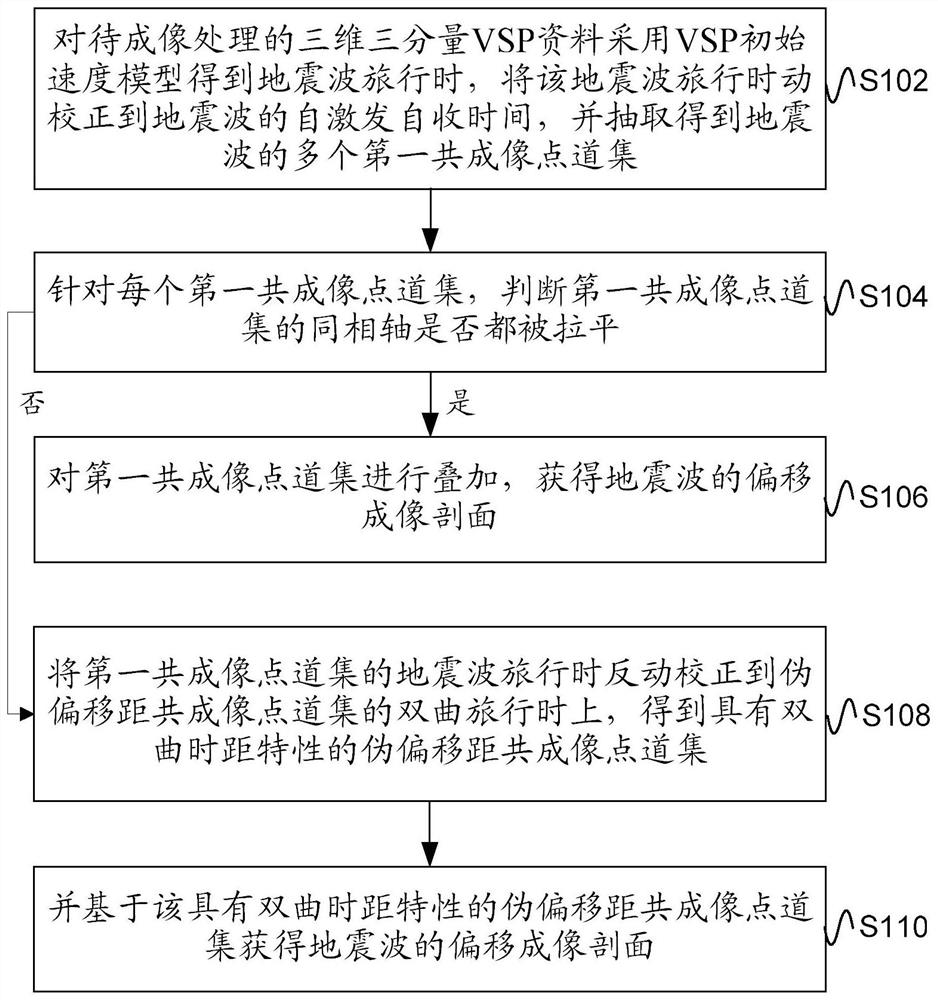
[0056] figure 1 Schematic flow chart of the 3D3C-VSP imaging processing method provided for the embodiment of this specification Figure 1 , this method can be applied in the related technical fields of 3D3C-VSP, such as image 3 As shown, the 3D3C-VSP imaging processing method includes the following steps:
[0057] S102, using the VSP initial velocity model to obtain the travel time of the seismic wave for the three-dimensional three-component VSP data to be imaged, correcting the travel time of the seismic wave to the self-excitation and self-receiving time of the seismic wave, and extracting multiple first common imaging points of the seismic wave set;
[0058] In the conventional common image point gather extraction process based on the VSP initial velocity model, such as figure 2 As shown, the shot point S excites seismic waves, and the seismic waves are scattered at the underground imaging point O (scattering point O for short), and are received by the underground re...
Embodiment 2
[0078] This embodiment is on the basis of embodiment one, to figure 1 The shown 3D3C-VSP imaging processing method is extended and supplemented.
[0079] Figure 4 Schematic flow chart of the 3D3C-VSP imaging processing method provided for the embodiment of this specification Figure II , step 108 is refined in this method, that is, the above step 108 may specifically include:
[0080] S108-2, keep the offset of the seismic wave unchanged, translate the shot point and receiver point to the pseudo-shot point and pseudo-receiver point on the surface, and project the pseudo-shot point and pseudo-receiver point to the imaging point of the seismic wave on the surface the distance is equal;
[0081] Specifically, such as image 3 As shown in , let the SR distance be x, keep the distance between SRs constant, and translate the SR to the detector side to S"R", where S" and R" are the pseudo-shot point and pseudo-receiver point respectively. C is the midpoint of S"R", and S"C=R"C=...
Embodiment 3
[0106] corresponding to the above figure 1 , Figure 4 , Figure 5 The described 3D3C-VSP imaging processing method is based on the same technical idea, and the embodiment of this specification also provides a 3D3C-VSP imaging processing device. Figure 8 A schematic diagram of the module composition of the 3D3C-VSP imaging processing device provided by the embodiment of this specification, which is used to execute figure 1 , Figure 4 , Figure 5 Describe the 3D3C-VSP imaging processing method as Figure 8 As shown, the device includes: gather extraction module 201, gather judgment module 202, imaging processing module 203 and reaction correction module 204;
[0107] The gather extraction module 201 uses the VSP initial velocity model to obtain the seismic wave travel time for the three-dimensional three-component VSP data to be processed, corrects the seismic wave travel time to the self-excitation and self-reception time of the seismic wave, and extracts multiple first...
PUM
 Abstract
Description
Claims
Application Information