Supercharge Your Innovation With Domain-Expert AI Agents!

A burner for a gas stove

A technology for burners and gas stoves, applied in the field of gas stoves, can solve the problems of waste of resources, low efficiency, excess secondary air, etc., and achieve the effects of improving thermal efficiency, accurate positioning, and improving combustion efficiency

Active Publication Date: 2021-11-02
NINGBO FOTILE KITCHEN WARE CO LTD
View PDF0 Cites 0 Cited by
  • Summary
  • Abstract
  • Description
  • Claims
  • Application Information

AI Technical Summary

Problems solved by technology

Among them, although the way of side air intake has the advantages of small air intake resistance and large air intake volume, there are still problems in the existing side air intake burners such as: due to the ejection effect of the combustion hot air flow, the internal and external fire The cover will entrain secondary air through the side air inlet of the air mixing chamber. The heat load of the inner ring is small, and the primary air coefficient is higher than that of the outer ring. However, the entrainment of secondary air is insufficient. In order to distribute the secondary air reasonably and achieve full combustion of the inner and outer rings, further improvements are needed.
[0003] In addition, most of the current gas cooker fire covers usually include an inner ring fire cover and an outer ring fire cover, and the heating method for the pot body is basically a combination of an external annular flame and an internal annular flame. The distance between the flame and the center of the bottom of the pot is relatively long, and the outer annular flame is sprayed outwards, so the bottom of the pot cannot be heated intensively, and the smoke formed by combustion stays at the bottom of the pot for insufficient time, resulting in low efficiency and waste of resources, and further improvement is needed

Method used


Image

  • A burner for a gas stove
  • A burner for a gas stove
  • A burner for a gas stove

Examples


Embodiment Construction

[0029] The present invention will be further described in detail below in conjunction with the accompanying drawings and embodiments.

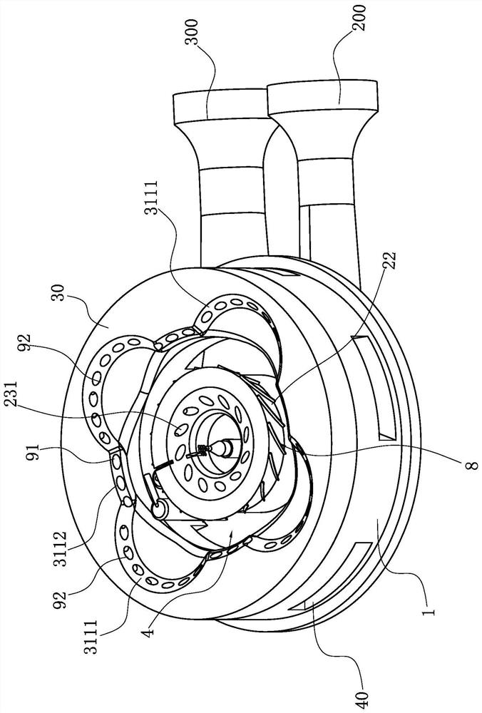
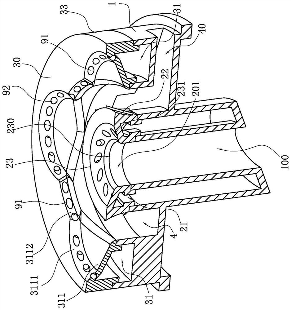
[0030] Such as Figure 1~5 As shown, it is the best implementation mode of the present invention. The burner used in the gas stove in this embodiment includes a base 1, which is arranged on the base 1 and forms a central mixing chamber with the base 1. The inner ring fire cover 2 of the gas chamber 21 is also arranged on the base 1, at the periphery of the inner ring fire cover 2, and forms an outer ring gas mixing chamber 31 with the base 1, the central gas mixing chamber 21 and the outer ring An air supply chamber 4 is formed between the annular air mixing chambers 31, and a plurality of radial secondary air supply passages 40 for connecting the air supply chamber 4 with the outside world are provided at intervals along the circumferential direction on the base 1, and the outer ring The air mixing chamber 31 is provided with fire outlets at...


PUM


Abstract

The invention relates to a burner for a gas stove, which includes a base, which is arranged on the base, and an inner ring fire cover forming a central gas mixing chamber between the base and the base, which is arranged on the base, and is located in the inner The periphery of the ring fire cover forms the outer ring fire cover of the outer ring air mixing chamber with the base, and the air supply chamber is formed between the central air mixing chamber and the outer ring air mixing chamber; the base is also arranged at intervals along the circumference. There are a plurality of radial secondary air supply passages for connecting the air supply chamber with the outside world, characterized in that: the outer ring air mixing chamber is provided with first fire outlets at intervals along the circumferential direction on the wall surface adjacent to the air supply chamber , the outer peripheral wall of the inner ring fire cover is provided with a deflector. Compared with the prior art, the advantage of the present invention is that in order to avoid the unreasonable distribution of the secondary air in the air supply cavity, the secondary air is carried out through the deflector. Divided flow, so that both the inner and outer rings can be fully burned, especially suitable for the outer ring fire cover with two rings of fire. The setting of the guide can avoid the mutual influence of the secondary air between the inner ring and the outer ring.

Description

technical field [0001] The invention relates to the field of gas stoves, in particular to a burner for a gas stove. Background technique [0002] The primary air coefficient of existing atmospheric stove burners is generally 0.4-0.7, and the premixed air cannot reach the air volume required for complete combustion. In addition to various factors, a certain amount of secondary air is required, and in order to reduce CO emission, secondary air supplement should be as sufficient as possible. At present, there are various ways of replenishing air for stove burners. Generally, there are side air intake and bottom air intake. The air inlet is supplemented with secondary air, and the way of lower air intake is to open the lower air inlet at the base base, and the air under the cooker is supplemented with secondary air through the lower air inlet. Among them, although the way of side air intake has the advantages of small air intake resistance and large air intake volume, there ar...

Claims


Application Information

Patent Timeline
Patent Type & Authority Patents(China)
IPC IPC(8): F23D14/04F23D14/26F23D14/46F23D14/58F23D14/64F23D14/66F23L9/00
CPCF23D14/04F23D14/26F23D14/46F23D14/58F23D14/64F23D14/66F23D2900/14062F23L9/00Y02E20/34
Inventor 史丽莎朱志新
Owner NINGBO FOTILE KITCHEN WARE CO LTD
Features
  • R&D
  • Intellectual Property
  • Life Sciences
  • Materials
  • Tech Scout
  • Unparalleled Data Quality
  • Higher Quality Content
  • 60% Fewer Hallucinations
Learn More