
Insulation ladle automatic turning cover and dumping device

A pouring device and pouring ladle technology, applied in metal processing equipment, manufacturing tools, casting molten material containers, etc., can solve the problems of poor thermal insulation effect, good loss rate, complex opening and closing structure, etc., to prolong the casting time and prolong the cooling. time, guarantee the effect of pouring temperature

Active Publication Date: 2021-08-17
湖南从义电炉设备有限公司
View PDF7 Cites 0 Cited by
  • Summary
  • Abstract
  • Description
  • Claims
  • Application Information

AI Technical Summary

Problems solved by technology

[0002] The molten iron ladle is a necessary production equipment in the production of metal casting. It is used to hold the molten metal. When working, the molten iron ladle is poured into the sand casting gate by tilting the ladle. Due to the extremely high temperature of the molten iron, the operation of the molten iron ladle is safe and convenient. Ladle lining material, ladle carrying capacity, etc. all need to be considered. In the actual production process, the molten iron ladle is suspended and moved. If the transfer path and transfer time are slightly longer, the temperature of the molten iron in the ladle will drop significantly. Fast, and it often occurs that the large ladle is transferred to the middle ladle, the middle ladle is divided into small ladles, and the small ladle starts to pour. During the transfer of molten steel, the temperature drops quickly, and the loss rate is good. In addition, most ladles are equipped with insulation covers, but Its opening and closing structure is complicated, and the heat preservation effect is poor

Method used


Image

  • Insulation ladle automatic turning cover and dumping device
  • Insulation ladle automatic turning cover and dumping device
  • Insulation ladle automatic turning cover and dumping device

Examples


Embodiment Construction

[0026] The preferred embodiments of the present invention will be described in detail below with reference to the accompanying drawings.

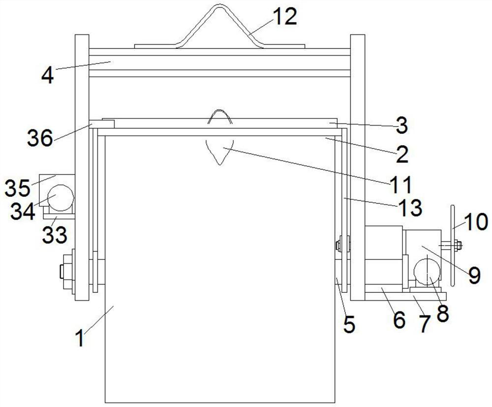
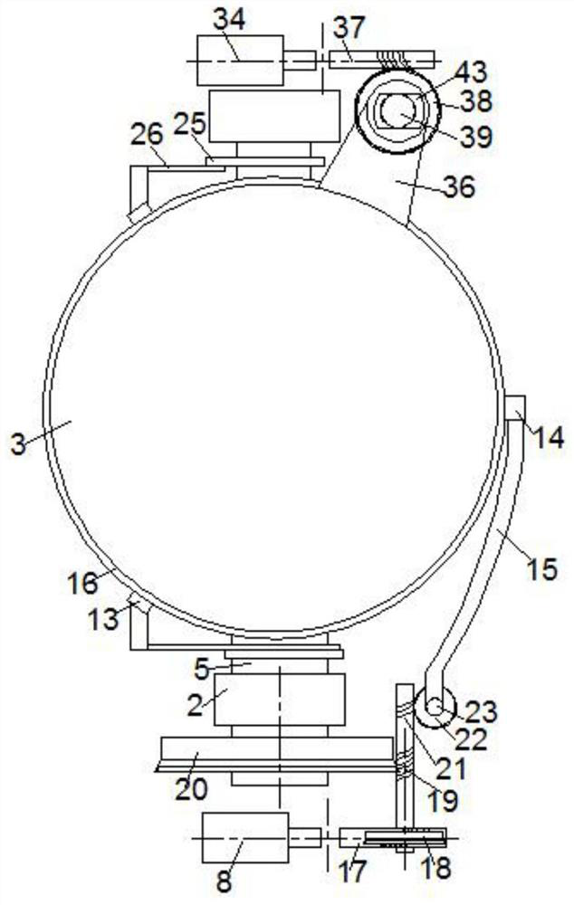
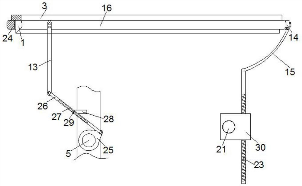
[0027] Such as Figure 1-6 Shown is a structural schematic diagram of the automatic cover turning and dumping device of the heat preservation ladle of the present invention; an automatic cover turning and dumping device of the heat preservation ladle of the present invention includes a ladle body 1 and a hanger 2, and the top of the ladle body 1 is movable A ladle cover 3 is installed, and the two sides of the ladle body 1 are symmetrically provided with an overturning shaft 5, and the overturning shaft 5 is movably hinged on the hanger 2, and the middle side wall of the ladle body 1 is provided with a discharge port 11. A ladle dumping device for connecting with the overturning shaft 5 is provided on the right side outer wall of the hanger 2, and the ladle dumping device includes a lateral reduction box 6 connected to the right side outer ...


PUM


Abstract

The invention discloses an automatic cover turning and dumping device for a thermal insulation ladle. There is an installation ring frame, and the outer wall on the left side of the hanger is provided with a turn cover motor, a worm gear box, a rotating shaft and the connection part on the ladle cover, which are connected in sequence, and a fixed block, a curved rod and a support rod are arranged on the installation ring frame; The ladle dumping device is connected with a worm gear elevator connected with a curved rod. The present invention is provided with a dumping motor and a cover turning motor on both sides of the hanger. The cover turning motor drives the ladle cover to rotate to open the cover and feed the material. At the same time as the main body is pouring and discharging, the installation ring frame and the ladle cover are controlled to rise and move synchronously with the pouring of the ladle body, which is beneficial to the insulation and discharge of the ladle, so as to ensure the pouring temperature of the molten metal, prolong the cooling time of the molten metal, and prolong the casting time to achieve the goal of safe production.

Description

technical field [0001] The invention belongs to the technical field of casting melt containers, such as ladles, tundishes, sprue cups or the like, and in particular relates to an automatic cover turning and pouring device for heat preservation ladles. Background technique [0002] The molten iron ladle is a necessary production equipment in the production of metal casting. It is used to hold the molten metal. When working, the molten iron ladle is poured into the sand casting gate by tilting the ladle. Due to the extremely high temperature of the molten iron, the operation of the molten iron ladle is safe and convenient. Ladle lining material, ladle carrying capacity, etc. all need to be considered. In the actual production process, the molten iron ladle is suspended and moved. If the transfer path and transfer time are slightly longer, the temperature of the molten iron in the ladle will drop significantly. Fast, and it often occurs that the large ladle is transferred to th...

Claims


Application Information

Patent Timeline
Patent Type & Authority Patents(China)
IPC IPC(8): B22D41/06B22D41/00
CPCB22D41/00B22D41/06
Inventor 朱从宜
Owner 湖南从义电炉设备有限公司
Learn More