Wet-type braking system of urban rail vehicle

A brake system and urban rail technology, applied in the field of rail transit, can solve the problems of reducing rail vehicles, long braking time, reducing wheel speed, etc., and achieve the effects of efficient and stable braking, easy disassembly, and convenient maintenance

Active Publication Date: 2020-06-12
李富盈
View PDF7 Cites 0 Cited by
  • Summary
  • Abstract
  • Description
  • Claims
  • Application Information

AI Technical Summary

Problems solved by technology

[0002] Rail vehicles are a fast and efficient way of travel. Nowadays, more people choose rail transit for travel. For example, trains, subways, bullet trains, and light rails are all rail vehicles; rail vehicles travel on tracks with less friction, so the speed Faster, but it also prevents rail vehicles from using the braking method of ordinary cars. Generally, air compression and electromagnetic induction are used to brake rail vehicles. This is also the reason why rail vehicles such as trains take a long time to brake.
[0003] Wet brakes are an important part of the wet brake system; as a braking system used by heavy vehicles on roads, wet brakes have a strong load-carrying capacity and good braking effect; however, wet brakes reduce the wheel speed through friction plates. Its wheels rub against the ground to brake, and it is not feasible to apply the existing wet brakes to rail vehicles in the same way, because the track surface is much smoother than the ground, and only reducing the wheel speed of the rail vehicle cannot effectively brake the track. Vehicle braking; therefore, it is necessary to set up a wet braking system specially applied to rail vehicles to achieve braking of rail vehicles through friction

Method used


Image

  • Wet-type braking system of urban rail vehicle
  • Wet-type braking system of urban rail vehicle
  • Wet-type braking system of urban rail vehicle

Examples


Embodiment Construction

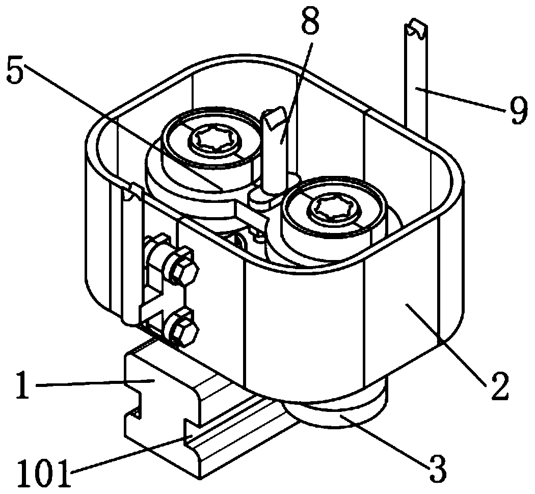
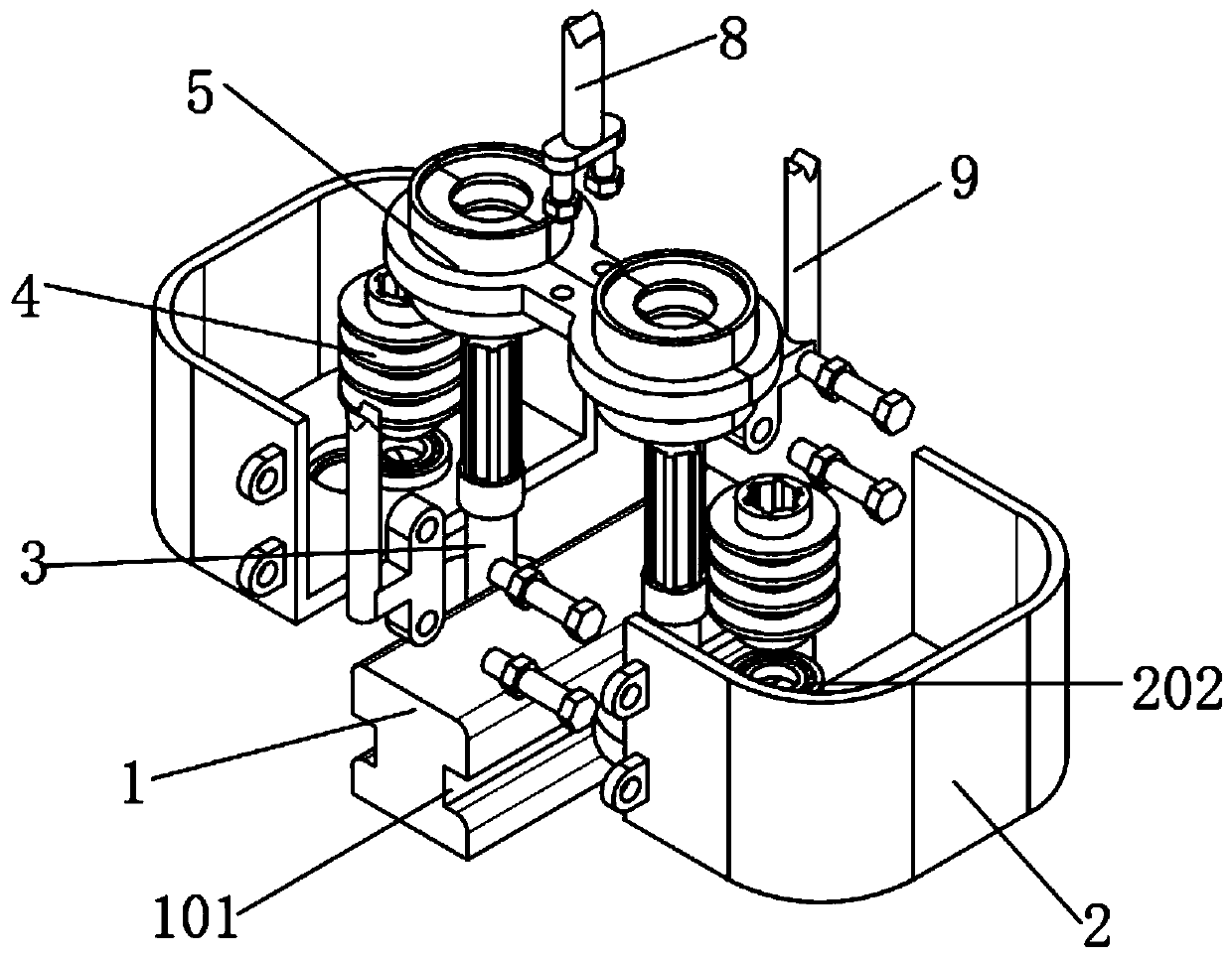
[0032] The embodiment of the invention discloses a wet brake system for urban rail vehicles, such as Figure 1-9 As shown, it includes an I-shaped track body 1 and a brake fixed on the bottom of the rail vehicle (not shown in the figure); Groove 101 (i.e. the two concave parts of the I-shaped), the upper surface of the outer casing 2 is provided with a bearing groove 201, the bearing groove 201 is fixedly connected with a rolling bearing 202, and the outer ring of the rolling bearing 202 is in contact with the bearing groove 201.

[0033] The lower surface of the outer casing 2 is provided with a limit ring 203, and the limit ring 203 and the bearing groove 201 are set to be connected and the axes coincide. The limit ring 203 is set to limit the rolling bearing 202, prevent the rolling bearing 202 from falling off from the bearing groove 201, and not Affecting the use of the rolling bearing 202 , the outer casing 2 is rotatably connected with the rolling wheel 3 through the ro...


PUM


Abstract

The invention relates to the field of rail transit, and particularly discloses a wet-type braking system of an urban rail vehicle. The wet-type braking system comprises a rail main body and a brake fixed to the bottom of a rail vehicle, wherein the brake comprises an outer shell and a brake assembly, a groove is formed in the rail main body, a bearing groove is formed in the outer shell, a rollingbearing is fixedly connected in the bearing groove, the outer shell is rotationally connected with a rolling wheel, the rolling wheel is fixedly connected with a connecting shaft, the top of the connecting shaft is fixedly connected with a supporting shaft, a spline shaft is fixedly connected to the top of the supporting shaft, the rolling wheel is in transmission connection with a friction cylinder, a spline hole is formed in the friction cylinder, the friction cylinder is fixedly connected with a friction disc, the brake assembly comprises a connecting frame and a friction semicircular cylinder, the connecting frame is fixedly connected with a semicircular ring, the semicircular ring is provided with an annular groove, the friction semicircular cylinder is fixedly connected with an annular boss, and the friction semicircular cylinder is fixedly connected with a friction semicircular sheet. The wet-type braking system of the urban rail vehicle has a function of braking the rail vehicle running on the rail main body through friction force.

Description

technical field [0001] The invention relates to the technical field of rail transit, in particular to a wet braking system for urban rail vehicles. Background technique [0002] Rail vehicles are a fast and efficient way of travel. Nowadays, more people choose rail transit for travel. For example, trains, subways, bullet trains, and light rails are all rail vehicles; rail vehicles travel on tracks with less friction, so the speed Faster, but it also prevents rail vehicles from using the braking method of ordinary cars. Generally, air compression and electromagnetic induction are used to brake rail vehicles. This is also the reason why rail vehicles such as trains take a long time to brake. [0003] Wet brakes are an important part of the wet brake system; as a braking system used by heavy vehicles on roads, wet brakes have a strong load-carrying capacity and good braking effect; however, wet brakes reduce the wheel speed through friction plates. Its wheels rub against the g...

Claims


Application Information

Patent Timeline
Patent Type & Authority Applications(China)
IPC IPC(8): B61H7/12
CPCB61H7/12
Inventor 李富盈黄世福李衡
Owner 李富盈
Why Eureka
Try Eureka