Connecting support and application thereof, driving device and water sports device
A technology for connecting brackets and driving devices, which is applied to water sports boards, motor vehicles, transportation and packaging, etc., can solve the problems of reducing the versatility of surfboard modules and difficult to realize the interchangeability of surfboard modules, and achieve the effect of interchangeability
- Summary
- Abstract
- Description
- Claims
- Application Information
AI Technical Summary
Problems solved by technology
Method used
Image
Examples
no. 1 example
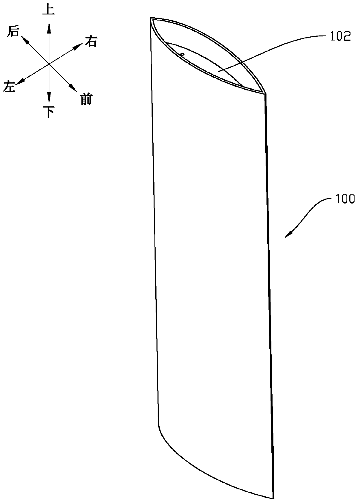
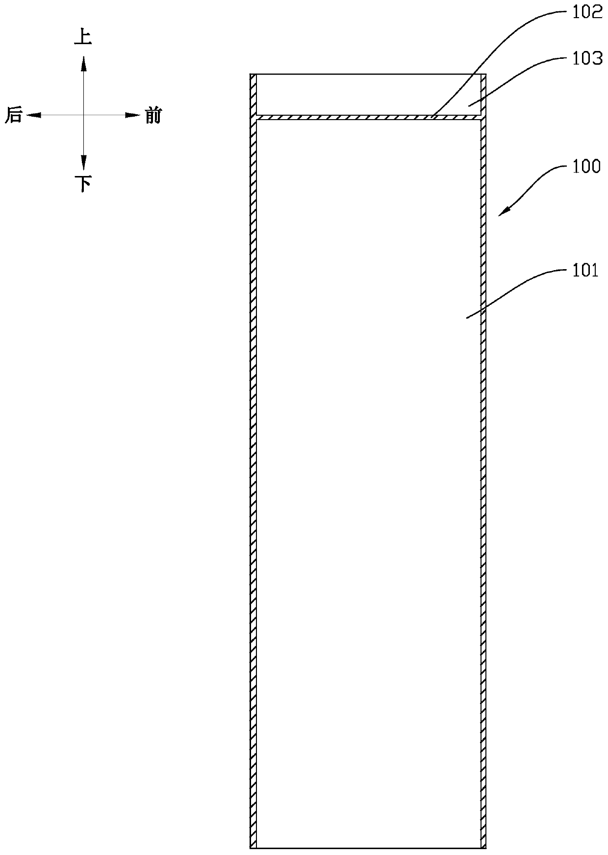
[0034] refer to figure 1 , figure 2 , figure 1 A schematic perspective view of a connecting bracket according to an embodiment of the present invention is shown, figure 2 show figure 1 The cross-sectional schematic diagram of the connecting bracket, the connecting bracket 100 of this embodiment is a long rod-shaped structure, which is used to connect the surfboard part and the power element part of the electric surfboard, specifically one end of the connecting bracket 100 (such as figure 1 The upper end of the ) is connected to the surfboard, and the other end (such as figure 1 The lower end of the middle) is connected to the power element. The connection bracket 100 can be a streamlined structure, for example, the cross section can be figure 1 The willow leaf shape in the structure can also be a water drop shape, etc., setting the willow leaf shape and other streamlined structures can reduce the resistance of the connecting bracket 100 when it moves in water on the one...
no. 2 example
[0037] refer to figure 2 , this embodiment is an improvement on the basis of the first embodiment. In this embodiment, a partition 102 is provided inside the connection bracket 100, and the partition 102 is connected to the width direction of the connection bracket 100 ( figure 2 parallel to the front-rear direction) and connected to the inner wall of the connection bracket 100, thereby separating the inner cavity of the connection bracket 100 into an upper insertion cavity 103 and a lower installation cavity 101, wherein the partition 102 is close to the top of the connection bracket 100, so that The installation cavity 101 for accommodating the battery has a larger volume.
no. 3 example
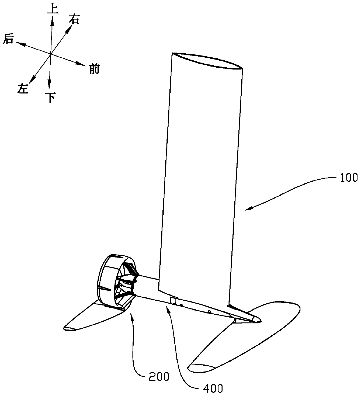
[0039] refer to image 3 , Figure 4 , image 3 shows a schematic perspective view of the driving device of the embodiment of the present invention, Figure 4 show image 3 An exploded schematic diagram of the drive unit. The driving device includes a connection bracket 100 , a power element 200 and a power supply assembly 300 . The power element 200 is connected to the connection bracket 100 .
[0040] In this embodiment, the power element 200 is connected to the lower end of the connecting bracket 100 and is used to push the whole driving device to move. The power element can be a propeller type power element, such as a motor and a propeller connected to the drive shaft of the motor, or a jet type power element. In some other embodiments, the power element 200 is connected through a power bracket 400, specifically, the power bracket 400 is image 3 It is placed in the front-back direction in the middle, and is connected with the lower end of the connecting bracket 100,...
PUM
 Abstract
Description
Claims
Application Information
 - R&D
- Intellectual Property
- Life Sciences
- Materials
- Tech Scout
- Unparalleled Data Quality
- Higher Quality Content
- 60% Fewer Hallucinations
Browse by: Latest US Patents, China's latest patents, Technical Efficacy Thesaurus, Application Domain, Technology Topic, Popular Technical Reports.
© 2025 PatSnap. All rights reserved.Legal|Privacy policy|Modern Slavery Act Transparency Statement|Sitemap|About US| Contact US: help@patsnap.com


