Two-stage vibration attenuation liquid-electric type active suspension with adjustable additional rigidity and damping and working method

A secondary vibration reduction, active suspension technology, applied in suspension, elastic suspension, transportation and packaging, etc., can solve the problems of constant damping stiffness, large inertial mass, large bushing spring, etc. Associated inertial forces, changing structural stiffness and damping, and downsizing effects

Active Publication Date: 2021-03-26
JIANGSU UNIV
View PDF15 Cites 11 Cited by
  • Summary
  • Abstract
  • Description
  • Claims
  • Application Information

AI Technical Summary

Problems solved by technology

In order to alleviate the problem that the equivalent inertial mass of the rotating motor actuator using a ball screw is too large, the Chinese patent application is 201810431437.9, which is entitled "An Active Suspension Using a Rubber Spring Coaxial with the Active Power Actuator" In the active suspension proposed in the literature, a rubber bushing spring is coaxially connected in series at the lower part of the active force actuator to form a two-stage damping rotating motor active suspension structure scheme. However, the dynamic deflection of the bushing spring needs to meet the rubber compression requirements. Therefore, it is necessary to reserve a certain bushing spring compression safety distance, resulting in a larger bushing spring, which in turn requires a larger suspension installation space between the vehicle body and the wheel. In addition, the damping stiffness of the additional rubber bushing spring is fixed. Unchanged, poor adaptability to vehicle driving conditions

Method used


Image

  • Two-stage vibration attenuation liquid-electric type active suspension with adjustable additional rigidity and damping and working method

Examples


Embodiment Construction

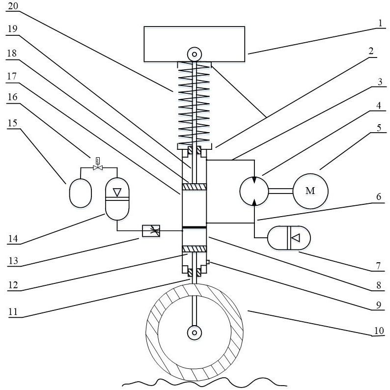
[0015] like figure 1 As shown, the orientation of the present invention is specified as follows: the wheel 10 is "below", and the vehicle body 1 is "above".

[0016] The secondary vibration-damping hydroelectric active suspension with adjustable additional stiffness and damping described in the present invention is installed between the wheel 10 and the vehicle body 1 above it, and is a primary vibration-damping structure composed of an active force actuator and a coil spring 20 and a secondary damping structure with adjustable damping stiffness, wherein the active force actuator includes an actuator hydraulic cylinder 17, a charge accumulator 7, a hydraulic pump / motor 4, and an electric / generator 5; the secondary vibration damping The structure includes a spring hydraulic cylinder 8 , an adjustable throttle valve 13 , a spring accumulator 14 , a solenoid valve 16 and an air storage tank 15 .

[0017] The actuator hydraulic cylinder 17 is vertically arranged, and a first pist...


PUM


Abstract

The invention discloses a two-stage vibration attenuation hydro-electric type active suspension with adjustable additional rigidity and damping and a working method, and belongs to the field of automobile suspensions. The suspension is composed of a first-stage vibration attenuation structure composed of an active force actuator and a spiral spring and a second-stage vibration attenuation structure with adjustable damping rigidity. The main power actuator comprises an actuator hydraulic cylinder, an oil supplementing energy accumulator, a hydraulic pump/motor and a motor/generator, and the second-stage vibration reduction structure comprises a spring hydraulic cylinder, an adjustable throttle valve, a spring energy accumulator, an electromagnetic valve and an air storage tank. The main power actuator is connected with an oil-gas spring in series. The suspension is provided with primary vibration reduction formed by the main power actuator and the spiral spring and secondary vibration reduction formed by the hydro-pneumatic spring, so that the associated inertia force of equivalent inertia mass of the primary vibration reduction structure is effectively reduced, the working states of the adjustable throttle valve and the electromagnetic valve can be conveniently adjusted according to the load state of an automobile, and the service life of the suspension is prolonged. And the rigidity and damping of the second-stage vibration reduction structure are changed.

Description

technical field [0001] The invention belongs to the field of automobile suspension, and relates to an active suspension structure with adjustable stiffness and damping and a working method thereof, which can realize active vibration reduction for automobiles. Background technique [0002] Active suspension has great advantages in vehicle vibration reduction. It can adjust the output force of the active force actuator according to the driving conditions of the vehicle, so as to take into account the ride comfort and handling stability of the vehicle. At present, there are several types of active force actuators, such as linear motor type, hydraulic type, and rotary motor type. The linear motor type has the simplest structure and the highest energy conversion efficiency, but its disadvantage is that the continuous output force density is small. Hydraulic actuators are generally divided into flow-regulated and pressure-regulated types, which require an external power source, s...

Claims


Application Information

Patent Timeline
Patent Type & Authority Applications(China)
IPC IPC(8): B60G17/015B60G17/02B60G17/04
CPCB60G17/0152B60G17/021B60G17/04B60G2202/154B60G2202/414
Inventor 陈士安王石力姚明蒋栋
Owner JIANGSU UNIV
Why Eureka
Try Eureka