
Bone end edge small bone sheet fixing device

A fixation device and small bone chip technology, which is applied in the direction of fixator, internal fixator, internal bone synthesis, etc., can solve the problem that small bone chips at the edge cannot be effectively fixed, and achieve the effect of preventing dislocation and improving strength

Pending Publication Date: 2022-07-15
陈聚伍
View PDF0 Cites 0 Cited by
  • Summary
  • Abstract
  • Description
  • Claims
  • Application Information

AI Technical Summary

Problems solved by technology

[0005] Aiming at the technical problem that small and thin bone fragments are formed after the fracture of the radial bone end, the bone fragments are very close to the edge, and belong to the parts that are prone to stress, so that the small bone fragments at the edge cannot be effectively fixed, the present invention provides a bone end marginal bone chip fixation device

Method used


Image

  • Bone end edge small bone sheet fixing device
  • Bone end edge small bone sheet fixing device
  • Bone end edge small bone sheet fixing device

Examples


Embodiment 1

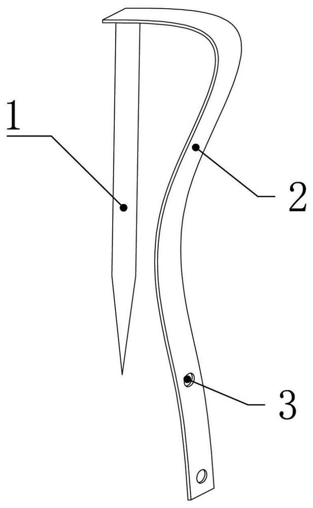
[0026] Example 1: A small bone fragment fixation device at the edge of the bone end, mainly designed for the technical problem that small bone fragments are formed after the fracture of the end of the flexible bone, and the bone fragments are very close to the edge, resulting in the inability to effectively fix the small bone fragments at the edge . This embodiment adopts the figure 1 the structure shown.

[0027] One way to solve this technical problem in the prior art is to insert a Kirschner wire in the center of the end of the radius and cut off the excess part, and the Kirschner wire is exposed outside the skin, leaving a wound that is prone to infection. Another similar method is to use a capless screw rod to connect the inner and outer bone parts with threads. This connection strength is weak, and the thread connection is easy to cause detachment problems, which is not conducive to limb activities during the rehabilitation period.

[0028] Because the bone fragments a...

Embodiment 2

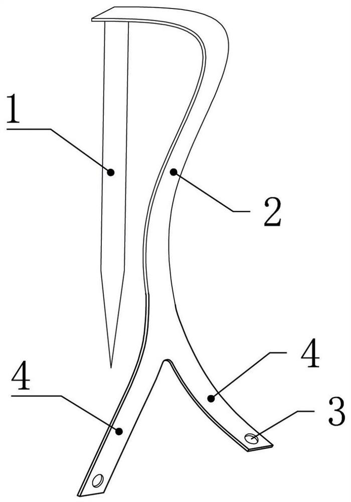
[0034] Embodiment 2: On the basis of Embodiment 1, there are further forked two auxiliary belts 4 at the end of the flexible connecting belt 2, such as figure 2 As shown, fixing holes 3 are respectively opened on each auxiliary belt 4 . The usage status of this embodiment is as follows Image 6 As shown, the two bifurcated auxiliary bands 4 are wrapped around the relatively smooth outer surface of the radial diaphysis. by one or two threaded rods or nails (such as Image 6 Fixing nails 9) fix each fixing hole 3, so that while the flexible connecting belt 2 has a traction effect, its distal ends are respectively fixed on the surface of the backbone, thereby improving the traction stability of the flexible connecting belt 2.

Embodiment 3

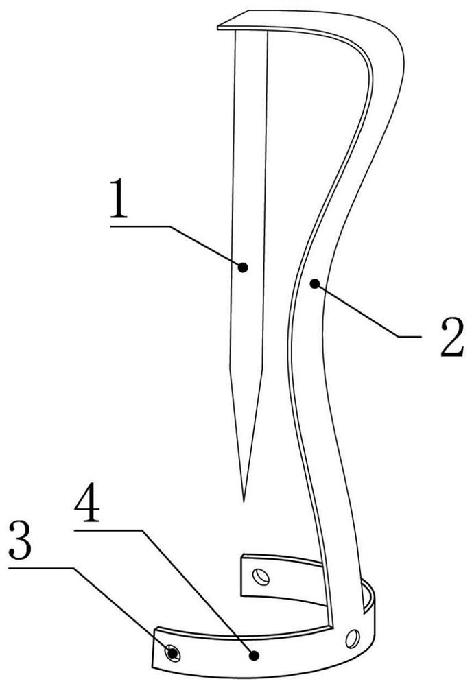
[0035] Example 3: On the basis of Example 1, one or two pieces of auxiliary tapes 4 are further extended and connected to the end of the flexible connecting tape 2, such as image 3 As shown, one or two auxiliary strips 4 and the flexible connecting strip 2 form an L-shaped or T-shaped structure. A fixing hole 3 is respectively opened on each auxiliary belt 4 . One or two bifurcated auxiliary bands 4 wrap around the relatively smooth outer surface of the radial shaft. Each fixing hole 3 is fixed by one or two screws or steel nails, so that while the flexible connecting belt 2 has a traction effect, the distal ends of the flexible connecting belt 2 are respectively fixed on the surface of the backbone, thereby improving the traction stability of the flexible connecting belt 2 .


PUM

PropertyMeasurementUnit
Thicknessaaaaaaaaaa

Abstract

The invention discloses a bone end edge small bone sheet fixing device which mainly comprises a stabilizing main nail and a flexible connecting band, one end of the flexible connecting band is fixed to the root of the stabilizing main nail, the stabilizing main nail is used for being inserted into a central hole in the bone end, and the flexible connecting band is used for being attached to the bone end and the surface of a backbone. Fixing holes are formed in the other end of the flexible connecting belt, and the fixing holes are fixed to the surface of the backbone through corresponding fixing nails. The stabilizing main nail is inserted into the drill hole along the end, only the end of the stabilizing main nail is kept to be located outside the drill hole, and the flexible connecting band is wide and flat, has a sufficient flexible function and can be completely attached to the end of the radius and the surface of the dry part, so that the bone surface is smooth and does not form an obviously upward bulge when the restraining and traction effects are achieved, and the fracture fracture is avoided. In the rehabilitation period, the limb movement function is not affected, and wound flatness recovery is not affected.

Description

technical field [0001] The invention belongs to the technical field of bone end edge fracture fixation devices, and in particular relates to a bone end edge small bone fragment fixing device. Background technique [0002] Comminuted fracture of distal radius is a common wrist injury, which is more common in middle-aged and elderly people, especially elderly women. Wrist deformity, fractures occur within 2-3 cm of the distal radius. After a comminuted fracture of the distal radius, the distal end of the radius splits into multiple small pieces and breaks with other radius parts to form a distal fracture, and the proximal segment of the radius (that is, the segment close to the fracture) loses its normal anatomical distance from the ulna. , the radius needs to be reduced and treated to gradually recover; the biggest difficulty in this situation is that the proximal fracture of the radius will be close to the ulna under the contraction of the interosseous membrane. Lateral di...

Claims


Application Information

Patent Timeline
IPC IPC(8): A61B17/68A61B17/82
CPCA61B17/683A61B17/82A61B2017/564
Inventor 陈聚伍
Owner 陈聚伍
Learn More