
Drive-by-wire chassis test bench

A test bench and chassis technology, applied in vehicle testing, machine/structural component testing, measuring devices, etc.

Pending Publication Date: 2020-06-12
清智汽车科技(苏州)有限公司
View PDF0 Cites 1 Cited by
  • Summary
  • Abstract
  • Description
  • Claims
  • Application Information

AI Technical Summary

Problems solved by technology

At present, due to the relative immaturity of brake-by-wire and steer-by-wire products, there is no corresponding testing equipment on the market. Therefore, most of the current testing is based on simulation and real vehicle or single-function product testing, which cannot quickly and effectively complete the whole set. Test detection of chassis system by wire

Method used


Image

  • Drive-by-wire chassis test bench
  • Drive-by-wire chassis test bench
  • Drive-by-wire chassis test bench

Examples


Embodiment Construction

[0021] Below in conjunction with the accompanying drawings, the present invention will be described in detail for the chassis test bench by wire.

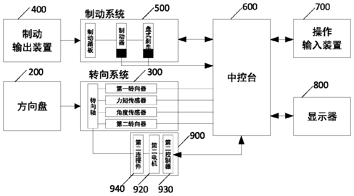
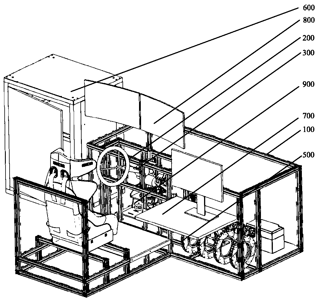
[0022] figure 1 It is a schematic diagram of the chassis test bench structure, figure 2 It is a mechanical structure diagram of the chassis by wire test bench, and the chassis by wire includes: bracket 100, steering wheel 200, steering system 300, brake output device 400, brake system 500, center console 600, operation input device 700 and Display 800.

[0023] Wherein the steering wheel 200, the steering system 300, the brake output device 400, the brake system 500, the center console 600, the operation input device 700 and the display 800 are all fixed on the bracket 100,

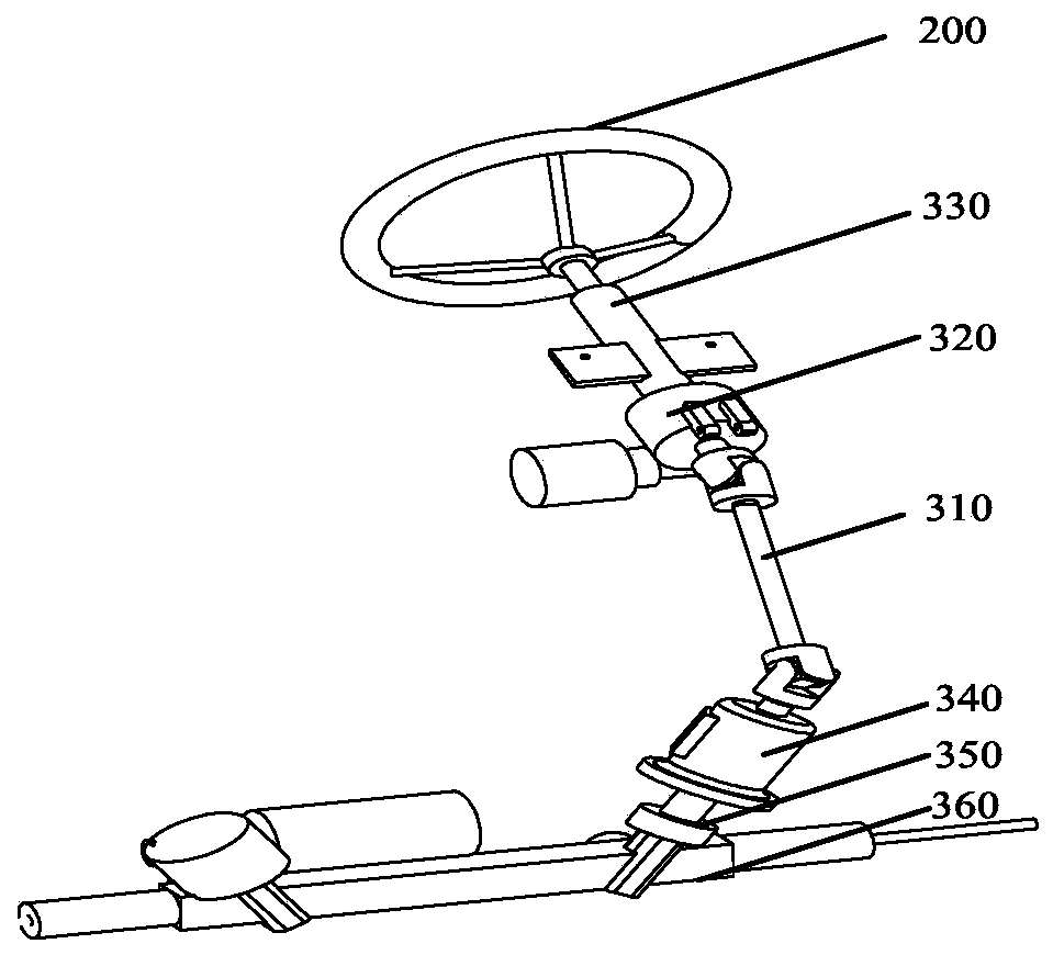
[0024] image 3 It is a structural diagram of the steering system, including the steering shaft 310, the first steering gear 320, the second steering gear 340, the torque sensor 330, the angle sensor 350 and the steering rod 360. The first steering gear 32...


PUM


Abstract

The invention discloses a drive-by-wire chassis test bench. The bench comprises a bracket, a steering wheel, a steering system, a braking system, a center console, an operation input device and a display, wherein the bracket is the integral frame structural member of the drive-by-wire chassis test bench, the steering wheel, the steering system, a brake output device and the braking system are fixed on the bracket, the steering wheel is connected with the input end of the steering system, the steering system is connected with the center console, the braking system is connected with the center console, and the operation input device and the display are in electric signal connection with the center console. The system can achieve the unified, comprehensive and efficient detection of the control algorithm and function detection of the intelligent drive-by-wire chassis.

Description

technical field [0001] The invention relates to a test stand for a control-by-wire chassis, in particular to a test stand for a control-by-wire chassis equipped with control algorithm verification and function tests for steering-by-wire and brake-by-wire. Background technique [0002] The intelligent control-by-wire chassis technology is an important assembly part in the future driverless technology, and the core technology of the control-by-wire chassis focuses on intelligent steering-by-wire technology and brake-by-wire technology. At present, due to the relative immaturity of brake-by-wire and steer-by-wire products, there is no corresponding testing equipment on the market. Therefore, most of the current testing is based on simulation and real vehicle or single-function product testing, which cannot quickly and effectively complete the whole set. Test and inspection of the ride-by-wire chassis system. Contents of the invention [0003] In order to solve the above prob...

Claims


Application Information

Patent Timeline
IPC IPC(8): G01M17/007
CPCG01M17/007
Inventor 张竞争刘晓辉王国岩刘彦明潘智慧陈文淼王琛詹君阳冬波张磊
Owner 清智汽车科技(苏州)有限公司
Learn More