Method and system for breathing monitoring

A technology of respiratory movement and monitoring device, applied in the system field of respiratory movement

Inactive Publication Date: 2020-06-12
IEE INT ELECTRONICS & ENG SA
View PDF12 Cites 2 Cited by
  • Summary
  • Abstract
  • Description
  • Claims
  • Application Information

AI Technical Summary

Problems solved by technology

However, this is almost impossible for testers

Method used


Image

  • Method and system for breathing monitoring
  • Method and system for breathing monitoring
  • Method and system for breathing monitoring

Examples


Embodiment Construction

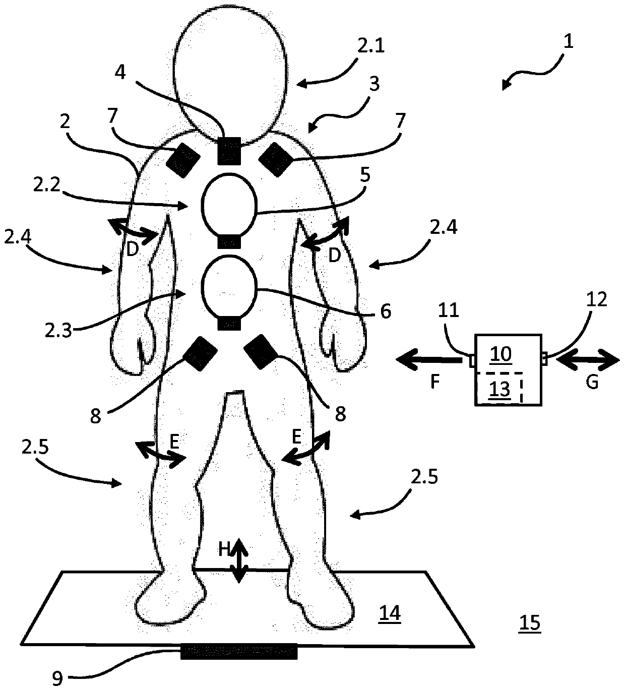
[0038] figure 1A system 1 of the present invention is schematically shown for simulating breathing movements (as well as other movements) of a human being, such as an infant or an adult. System 1 includes a mannequin 2 that is sized and shaped like a human. Such as figure 1 As shown, the mannequin 2 comprises a head region 2.1, a chest region 2.2, an abdomen region 2.3, two arm regions 2.4 and two leg regions 2.5. The system 1 also comprises an actuator system 3 which in this embodiment is arranged entirely inside the manikin 2 . The actuator system 3 comprises a head actuator 4 , a chest actuator 5 , an abdomen actuator 6 , two arm actuators 7 and two leg actuators 8 . It should be understood that the actuators 4-8 are shown schematically and that their size, shape and position may vary from actual. While the head actuator 4, arm actuator 7, and leg actuator 8 may, for example, be electric actuators, the chest actuator 5 and abdomen actuator 6 may be electric actuators co...


PUM


Abstract

The invention relates to a system (1) for simulating a breathing motion (B, C) of a living being (30) the system (1) comprising a manikin (2) representing the living being (30) and having a chest region (2.2) and an abdominal region (2.3). In order to provide means for reliably and realistically verifying the functionality of a breathing monitoring device, the system further comprises: an actuatorsystem (3) configured to generate a chest motion (B) in the chest region (2.2) and an abdominal motion (C) in the abdominal region (2.3); and a control unit (10) configured to independently control the chest motion (B) and the abdominal motion (C) to represent the breathing motion.

Description

technical field [0001] The present invention relates to a system for simulating breathing movements of living beings. The invention also relates to a method for programming such a system and a method for testing a monitoring device for monitoring the respiratory movement of a living being. Background technique [0002] Various methods for monitoring human respiration are known in the art. Such monitoring may be performed in order to assess the fitness of an athlete, assess driver or pilot fatigue, monitor sleep behavior or identify breathing abnormalities. Some of these methods are contact methods that, for example, require a person to don a mask and / or stretch a resistance band. In addition to this, there are contactless methods. The latter method is mainly radar-based and uses one or several radar transceivers. In addition to this, there are also methods which rely on the optical recognition of breathing movements. These methods are used, for example, in automotive ap...

Claims


Application Information

Patent Timeline
Patent Type & Authority Applications(China)
IPC IPC(8): G09B23/32
CPCG09B23/32
Inventor D·塔塔林诺夫C·沃特根P·拉森U·卡拉哈萨诺维奇F·勒莫因
Owner IEE INT ELECTRONICS & ENG SA
Why Eureka
Try Eureka