Nut riveting device for machining

A kind of machining and nut technology, applied in the field of machining, can solve the problems of increasing the work intensity of workers, reducing production efficiency, affecting the beauty and firmness of nuts, etc.

Inactive Publication Date: 2020-06-16
WUHU INST OF TECH
View PDF8 Cites 3 Cited by
  • Summary
  • Abstract
  • Description
  • Claims
  • Application Information

AI Technical Summary

Problems solved by technology

[0003] The existing nut riveting device in mechanical production is as described in the invention patent "Nut Riveting Device" with the application number "201710242954.7". By manually holding the left handle and the right handle, the spindle of the thimble and the nut is roughly positioned, and the thimble falls. to the main shaft, and then the oil cylinder pulls the riveting rod to move, and uses the principle of leverage to drive the left and right jaws to shrink inward, thereby driving the left riveting head and the right riveting head to rivet the nut. However, in this scheme, the device is placed on the nut manually Riveting nuts will increase the work intensity of workers after long-term operation and reduce production efficiency, and when riveting nuts of different sizes, the riveting positions of the nuts on the left riveting head and the right riveting head are different. After the nut is riveted, it will affect the beauty and firmness of the nut

Method used


Image

  • Nut riveting device for machining
  • Nut riveting device for machining
  • Nut riveting device for machining

Examples


Embodiment Construction

[0025] In order to make the above objects, features and advantages of the present invention more comprehensible, specific implementations of the present invention will be described in detail below in conjunction with the accompanying drawings. In the following description, numerous specific details are set forth in order to provide a thorough understanding of the present invention. However, the present invention can be implemented in many other ways different from those described here, and those skilled in the art can make similar improvements without departing from the connotation of the present invention, so the present invention is not limited by the specific implementations disclosed below.

[0026] It should be noted that when an element is referred to as being “fixed” to another element, it can be directly on the other element or there can also be an intervening element. When an element is referred to as being "connected to" another element, it can be directly connected ...


PUM


Abstract

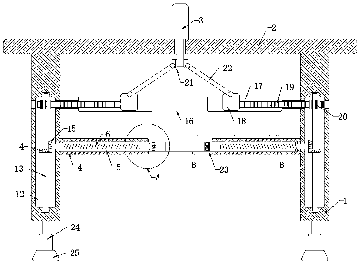
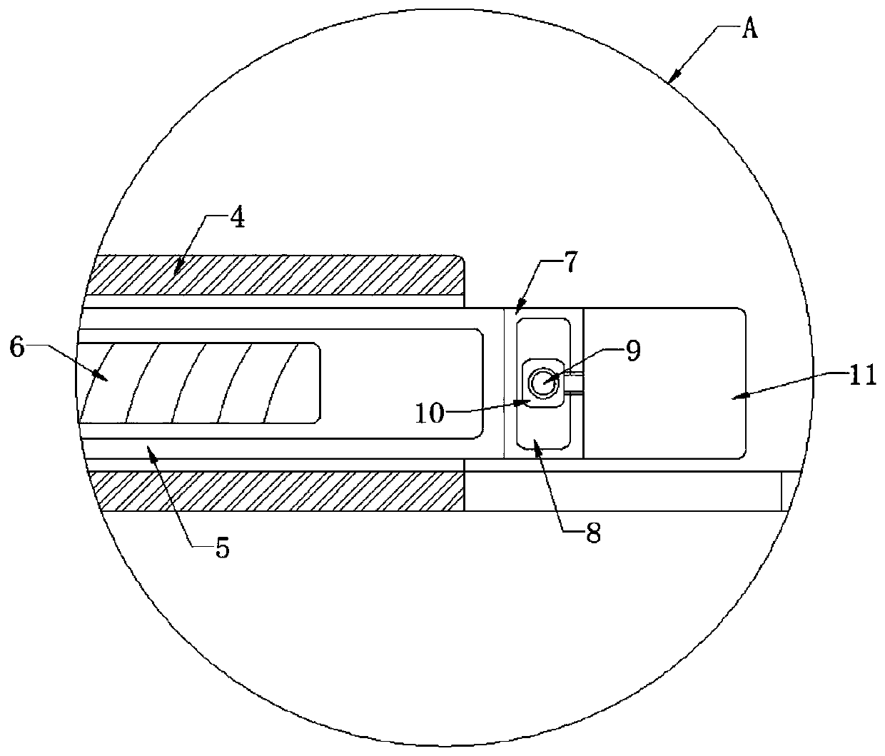
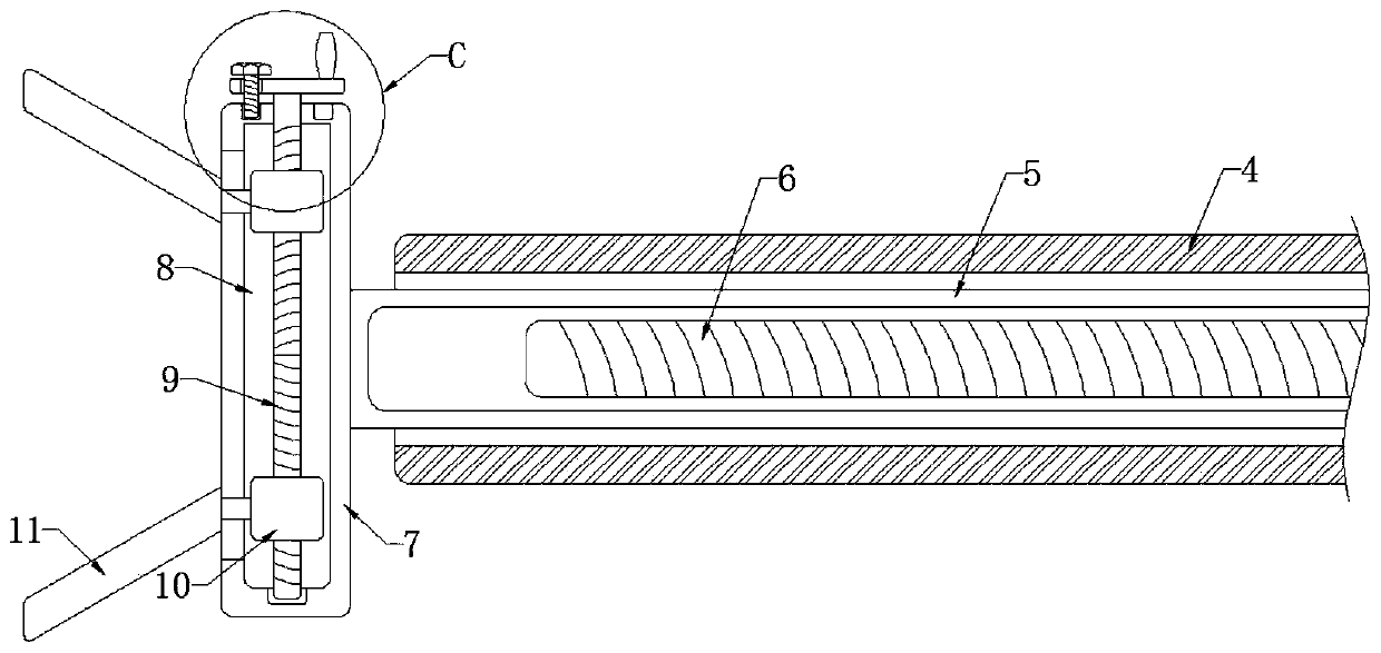
The invention discloses a nut riveting device for machining. The nut riveting device comprises two vertical plates, wherein the opposite side walls of the two vertical plates are fixedly connected with fixed cylinders, the inner walls of the fixed cylinders are slidably connected with movable cylinders, the ends, away from the side walls of the fixed cylinders, of the movable cylinders are fixedlyconnected with first clamping plates, the side wall of each first clamping plate is in sliding connection with two second clamping plates which are obliquely arranged, and an adjusting device for adjusting the distance between the two second clamping plates is installed on each first clamping plate. According to the device, by arranging an air cylinder, a connecting column, a movable rod, a sliding block, a rack, a gear, a vertical rod, a first bevel gear and a second bevel gear, the movable end of the air cylinder moves downwards to enable a lead screw fixedly connected with the side wall ofthe second bevel gear to rotate, so that the movable cylinders slide on the inner walls of the fixed cylinders, and then the first clamping plates clamp a nut in the horizontal direction, and the situation that the nut is riveted in a left-right inclined mode, and consequently the attractiveness and firmness of the riveted nut are affected is avoided.

Description

technical field [0001] The invention relates to the technical field of machining, in particular to a nut riveting device for machining. Background technique [0002] A nut is a part that is screwed together with a bolt or a screw for fastening. In mechanical production, many parts are often fixedly connected through nuts. However, in order to ensure the stability of the nut connection, it is necessary to tighten the nut. Riveting is carried out in order to secure the nut axially. [0003] The existing nut riveting device in mechanical production is as described in the invention patent "Nut Riveting Device" with the application number "201710242954.7". By manually holding the left handle and the right handle, the spindle of the thimble and the nut is roughly positioned, and the thimble falls. to the main shaft, and then the oil cylinder pulls the riveting rod to move, and uses the principle of leverage to drive the left and right jaws to shrink inward, thereby driving the le...

Claims


Application Information

Patent Timeline
Patent Type & Authority Applications(China)
IPC IPC(8): B21D39/00B21D43/00
CPCB21D39/00B21D43/003
Inventor 李超高天铱马梦婷王颖郑梦婷
Owner WUHU INST OF TECH
Why Eureka
Try Eureka