Spindle brake device of spinning machine
A brake device and spinning machine technology, applied in the direction of textiles and papermaking, can solve problems such as complex structure and large size
- Summary
- Abstract
- Description
- Claims
- Application Information
AI Technical Summary
Problems solved by technology
Method used
Image

Examples
no. 1 Embodiment approach >
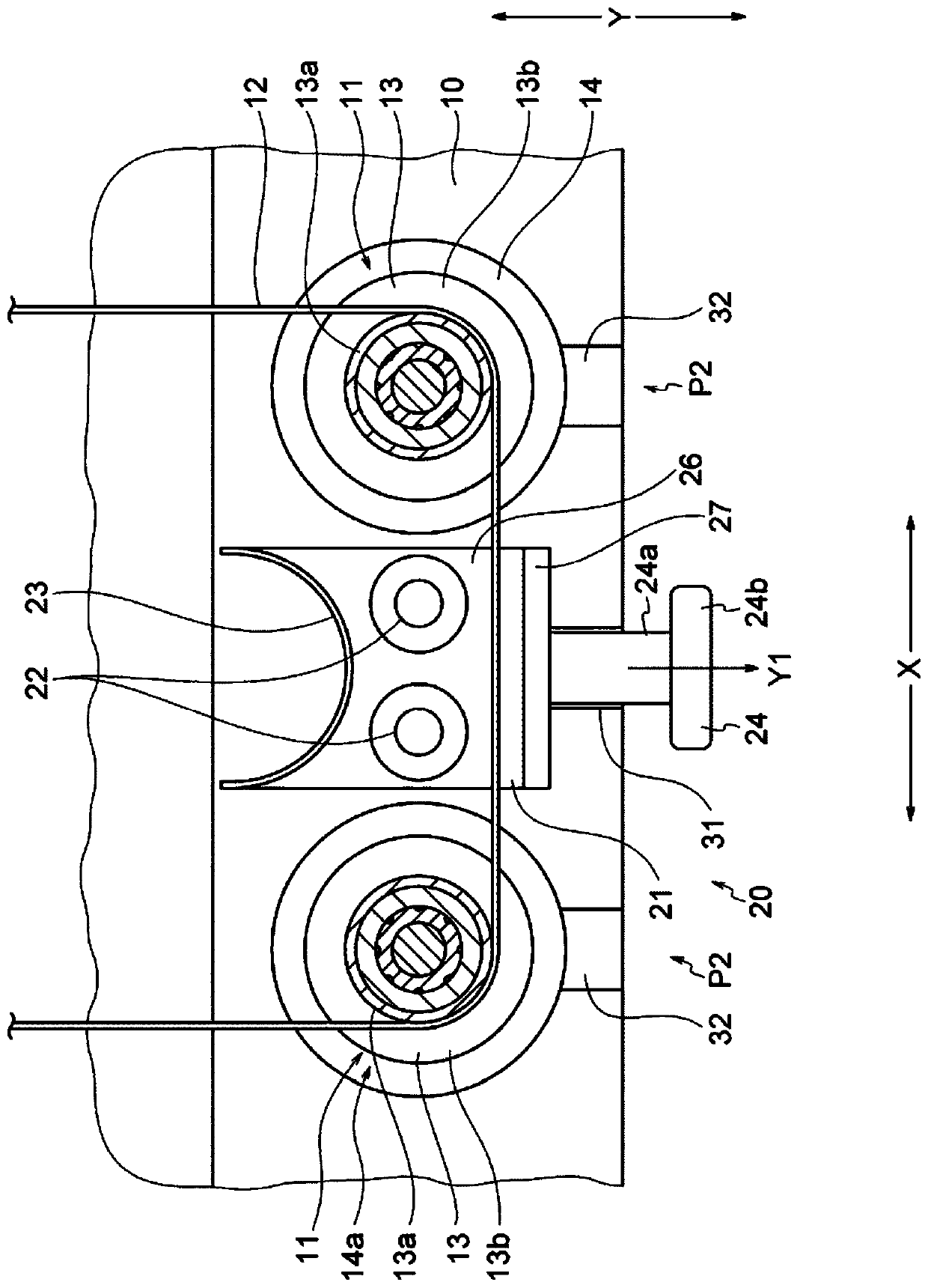
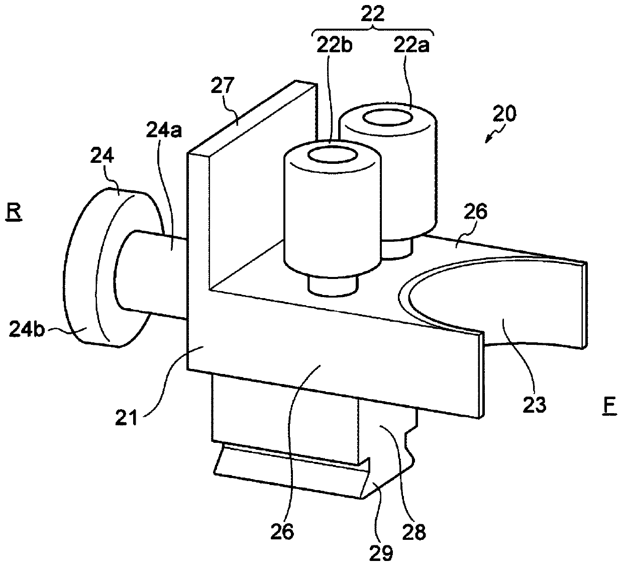
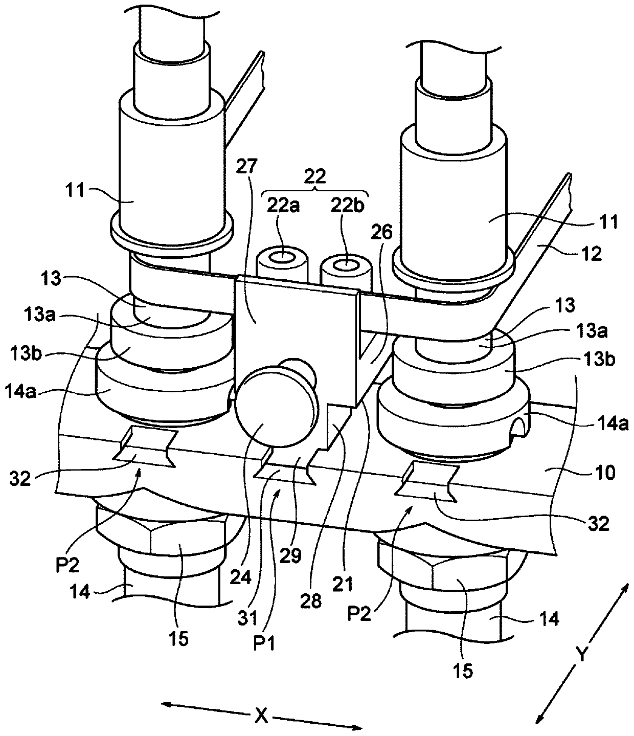
[0031] figure 1 It is a partially cutaway plan view showing the structure of the spindle brake device of the spinning machine according to the first embodiment, figure 2 yes means figure 1 A perspective view of the structure of the main part of the spindle braking device. in addition, image 3 It is a perspective view showing the configuration of the spindle brake device of the spinning machine according to the first embodiment.
[0032] In this first embodiment, the structure of the spindle device of the spinning machine will be described first, and then the structure of the spindle braking device of the spinning machine according to the first embodiment will be described. The spindle braking device is a device attached to the spindle device.
[0033] (Structure of the spindle device)
[0034] Such as Figure 1 ~ Figure 3 As shown, the spindle device of the spinning machine includes two spindles 11 adjacent in the longitudinal direction X of the spindle guide 10 and a ...
no. 2 Embodiment approach >
[0057] Figure 6 It is a perspective view showing the structure of the spindle braking device of the spinning machine according to the second embodiment, Figure 7 It is a side view showing the structure of this spindle braking device. In addition, in Figure 6 and Figure 7In , the display of the spindle tape 12 is omitted. In addition, in this 2nd Embodiment, the same code|symbol is attached|subjected and demonstrated to the part which is the same as or corresponds to the structure of the said 1st Embodiment.
[0058] In the spindle braking device 20 according to the second embodiment, the shapes of the guide grooves 31 and 32 formed on the spindle guide rail 10 as guide parts, the shape of the brake body 121 fitted therein, and the The bracket 35 is different from the first embodiment described above in these points.
[0059] When viewed in the width direction Y of the spindle guide rail 10, the guide groove 31 is formed in a rectangular cross section, and the guide gr...
no. 3 Embodiment approach >
[0065] Figure 10 It is a perspective view which shows the structure of the main part of the spindle braking apparatus concerning 3rd Embodiment. In addition, in this 3rd Embodiment, the same code|symbol is attached|subjected and demonstrated to the part which is the same as or corresponds to the structure of the said 1st Embodiment.
[0066] Such as Figure 10 As shown, a positioning pin 41 is provided on the main body 221 of the brake. In addition, a fitting portion 30 protruding downward is integrally formed on the bottom block portion 228 of the brake main body 221 . The fitting portion 30 is integrally formed at the lowermost portion of the bottom block portion 228 . The fitting portion 30 is a portion fitted into the guide groove 31 of the spindle guide rail 10 . The positioning pin 41 is configured to be detachable from a positioning hole described later. The positioning pin 41 is arranged so as to protrude toward the front side F of the brake main body 221 . In a...
PUM
 Abstract
Description
Claims
Application Information
 - R&D Engineer
- R&D Manager
- IP Professional
- Industry Leading Data Capabilities
- Powerful AI technology
- Patent DNA Extraction
Browse by: Latest US Patents, China's latest patents, Technical Efficacy Thesaurus, Application Domain, Technology Topic.
© 2024 PatSnap. All rights reserved.Legal|Privacy policy|Modern Slavery Act Transparency Statement|Sitemap