Double-view-field optical coherence tomography imaging system and material thickness detection method

A technology of optical coherence tomography and optical coherence tomography, which is applied in measurement devices, optical devices, instruments, etc., to achieve good thickness measurement capability, high measurement accuracy, and reduce the effects of human subjective factors.

Active Publication Date: 2020-06-16
SUZHOU UNIV
View PDF7 Cites 2 Cited by
  • Summary
  • Abstract
  • Description
  • Claims
  • Application Information

AI Technical Summary

Problems solved by technology

However, due to the limited imaging depth, OCT is currently only used to measure the thickness of transparent materials

Method used


Image

  • Double-view-field optical coherence tomography imaging system and material thickness detection method
  • Double-view-field optical coherence tomography imaging system and material thickness detection method
  • Double-view-field optical coherence tomography imaging system and material thickness detection method

Examples


Embodiment 1

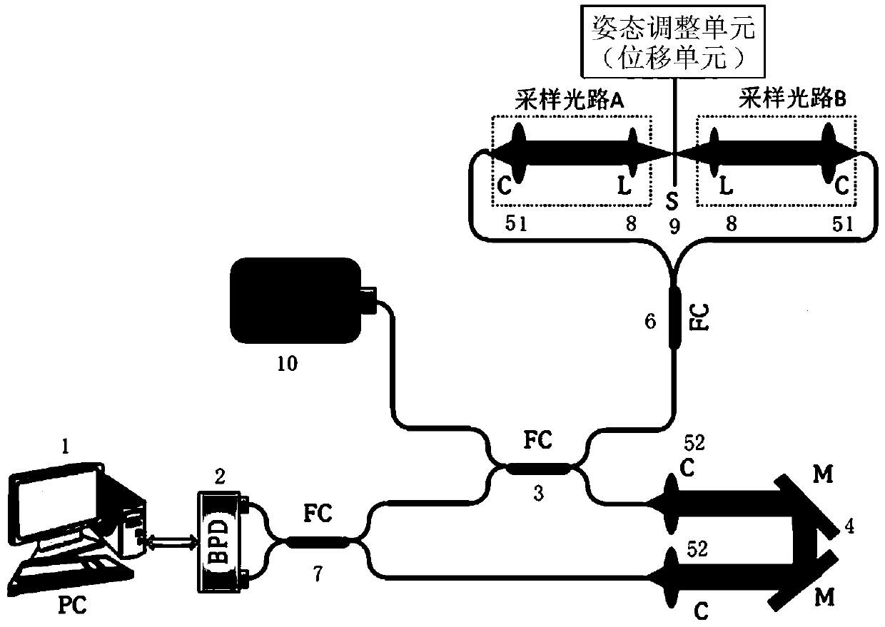
[0080] The PC 1 cooperates with the sample arm in the DSV-OCT system and the attitude adjustment unit of the sample placement platform to perform B-scan and C-scan, and realize data acquisition and processing. The data acquisition card set in the PC 1 uses the external k clock provided by the laser source as the sampling clock to perform analog-to-digital conversion on the signal output by the balanced detector, and the obtained interference spectrum signals are evenly distributed in the wave number space and stored in the Computer memory for subsequent Fourier transform calculations. The data acquisition program is built on the LabVIEW platform, which is used to collect data and control the movement of the electric translation platform to realize B-scan and C-scan. Data processing is mainly to convert the interference signal into a signal in the sample depth domain by performing spectral shaping, Fourier transform and removing fixed pattern noise on the detected interference ...

Embodiment 2

[0095] On the basis of Embodiment 1, the ability of the DSV-OCT system to generate a two-dimensional thickness map. Customize a 1-inch opaque disc engraved with a circular wall (inner diameter: 2mm, outer diameter: 3mm, height: 0.3mm) as a sample. A 4mm square area was scanned with the DSV-OCT system, and the scanned original 3D image is as follows Figure 7 As shown in (a) figure. The overall contours of the two surfaces can be clearly seen from the 3D graphics. Figure 7 The picture in (b) is Figure 7 An example of a cross-sectional image at the dotted rectangular box in (a) panel. Before computing the thickness, mean filtering was used to further reduce noise. Figure 8 Figure (a) plots the contours of the two surfaces, and the material thickness calculated using formula (4) as Figure 8 As shown in (b) figure. There are some slight fluctuations in the thickness, indicating that the surface roughness of the material is not very good.

[0096] In addition, DSV-OCT sy...


PUM


Abstract

The invention relates to a double-view-field optical coherence tomography imaging system and a material thickness detection method. The swept-frequency optical coherence tomography imaging system comprises a scanning imaging system and a swept-frequency light source for providing a light source for the scanning imaging system. The scanning imaging system comprises a sample arm and a reference armwhich are correspondingly connected with the swept-frequency light source respectively, and the swept-frequency light source provides a sampling light source or a reference light source for the samplearm and the reference arm respectively; the sample arm further corresponds to a sample placing platform, and the sample placing platform comprises a posture adjusting unit for positioning of a to-be-detected sample. Light returned by the sample arm and light returned by the reference arm interfere with each other to form interference signals, and the interference signals are detected by a balancephotoelectric detector and transmitted back to a PC. According to a double-side-view OCT system provided by the invention, the OCT technology is further expanded to the thickness measurement of the opaque material, so that the precision of measuring the thickness of the opaque material is improved.

Description

technical field [0001] The invention relates to the technical field of material detection, in particular to the technical field of non-transparent material thickness detection, and in particular to a dual-field optical coherence tomography imaging system and a non-transparent material thickness detection method. Background technique [0002] Optical coherence tomography (Optical Coherence Tomography, OCT) is a low-coherence optical interference imaging technology, which can scan and image optical scattering media such as biological tissues, and the obtained image resolution can reach the micron level. OCT has a new technical method, which has the advantages of non-contact, non-invasive, non-invasive and high resolution. According to its imaging mechanism, this technology is very suitable for imaging and thickness measurement of multilayer structures, therefore, OCT has been widely used in medical diagnosis. So far, OCT has been successfully applied to ophthalmic imaging as ...

Claims


Application Information

Patent Timeline
Patent Type & Authority Applications(China)
IPC IPC(8): G01B11/06
CPCG01B11/06G01B11/0675
Inventor 莫建华吴倩
Owner SUZHOU UNIV
Why Eureka
Try Eureka