
LoRa power detection method and device and transmitting circuit

A technology of power detection circuit and transmission circuit, which is applied in the field of communication, can solve the problem of low power, achieve the effect of alleviating the inaccuracy of transmission power and improving network reliability

Pending Publication Date: 2020-06-16
青岛合启立智能科技有限公司
View PDF7 Cites 1 Cited by
  • Summary
  • Abstract
  • Description
  • Claims
  • Application Information

AI Technical Summary

Problems solved by technology

For example, the TX Power is set to 20dBm, but due to the attenuation of the transmission path and the influence of antenna gain, the actual transmitted power is 2-8dB lower

Method used


Image

  • LoRa power detection method and device and transmitting circuit
  • LoRa power detection method and device and transmitting circuit
  • LoRa power detection method and device and transmitting circuit

Examples


Embodiment Construction

[0044] In order to make the purpose, technical solutions and advantages of the embodiments of the present application clearer, the technical solutions of the present application will be clearly and completely described below in conjunction with the accompanying drawings. Obviously, the described embodiments are part of the embodiments of the present application, not all of them. the embodiment. Based on the embodiments in this application, all other embodiments obtained by persons of ordinary skill in the art without making creative efforts belong to the scope of protection of this application.

[0045] The terms "including" and "having" mentioned in the embodiments of the present application and any variations thereof are intended to cover non-exclusive inclusion. For example, a process, method, system, product or device comprising a series of steps or units is not limited to the listed steps or units, but optionally also includes other unlisted steps or units, or optionally ...


PUM


Abstract

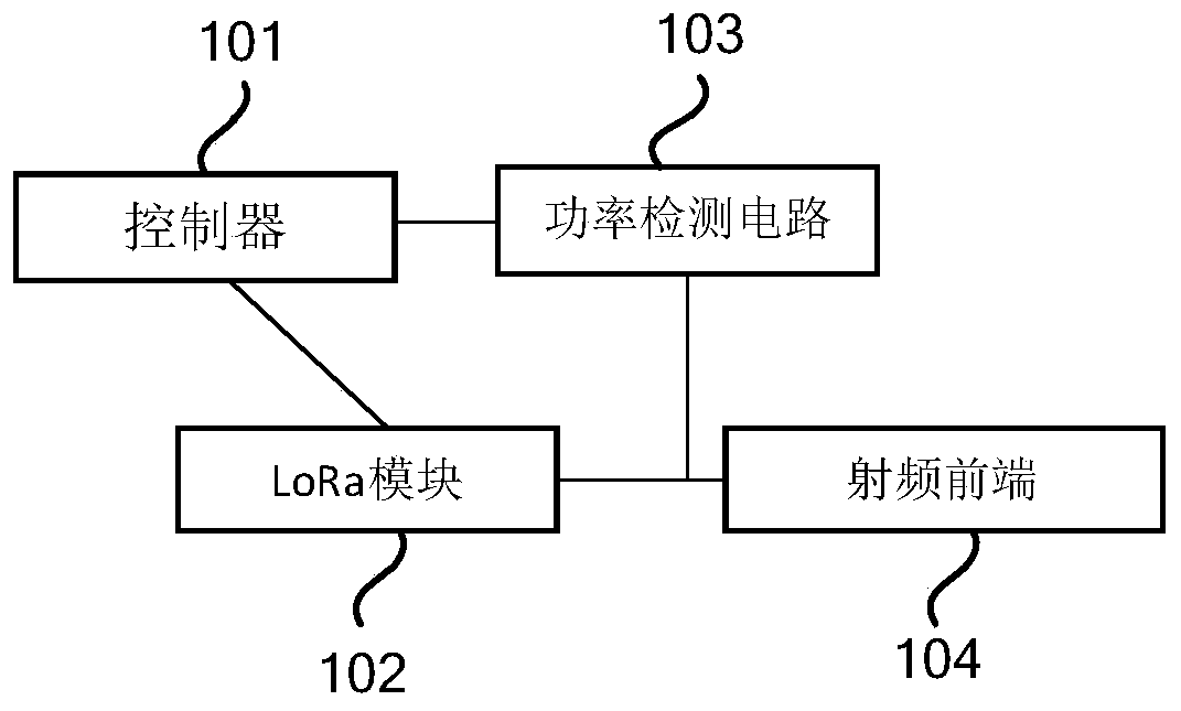
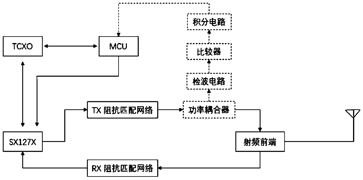
The invention provides a LoRa power detection method and device and a transmitting circuit, and relates to the technical field of communication. The LoRa power detection method and device are appliedto the transmitting circuit, the transmitting circuit comprises a LoRa module, a power detection circuit and a radio frequency front end, the power detection circuit is arranged at the position closeto the radio frequency front end, and the method comprises the steps of: obtaining the actual value of the current transmitting power through the power detection circuit; detecting the actual value ofthe current transmitting power to obtain a power error value; and based on the power error value, performing emission compensation through the LoRa module. The condition of inaccurate transmitting power caused by transmitting power open-loop control is relieved; and the network reliability of the LoRa system is improved.

Description

technical field [0001] The present invention relates to the field of communication technology, in particular to a LoRa power detection method, device and transmission circuit. Background technique [0002] The current LoRa radio frequency transmission power control is an open-loop mode, and a fixed level of transmission power is performed through software configuration, and there is no detection of the actual transmission power of the air interface. Due to uncertain factors such as the network environment, radio frequency channel, and antenna, the actual transmit power of the air interface will deviate greatly from the set power level. For example, the TX Power is set to 20dBm, but due to the attenuation of the transmission path and the influence of antenna gain, the actual transmitted power is 2-8dB lower. Contents of the invention [0003] The purpose of the present invention is to provide a LoRa power detection method, device and transmission circuit to alleviate the i...

Claims


Application Information

Patent Timeline
Patent Type & Authority Applications(China)
IPC IPC(8): H04W52/10H04W52/20H04B17/10
CPCH04W52/10H04W52/20H04B17/102
Inventor 史春杰康波乔彬刘若飞程凯郭志波吴修福张庭栋闫敬鹏叶胜林谭亮
Owner 青岛合启立智能科技有限公司
Learn More