Supercharge Your Innovation With Domain-Expert AI Agents!

Main line rotating ring structure used for being connected with pole tip

A swivel, main line technology, applied in the application, fishing rod, fishing and other directions, can solve the problems of reducing the main line tension, loss, loss of the entire line group of the hollow line, etc., to ensure the rotation function and avoid damage.

Pending Publication Date: 2020-06-19
李志新
View PDF0 Cites 0 Cited by
  • Summary
  • Abstract
  • Description
  • Claims
  • Application Information

AI Technical Summary

Problems solved by technology

When the main line group is tied to the hollow wire with a knot to realize the connection between the main line group and the rod tip, there is a defect that it takes time and effort to disassemble the main line group after use; When realizing the connection between the main line group and the rod tip, the main line group has been wound and disassembled for many times, which will cause deformation and damage to the main line part of the hollow line, which greatly reduces the tension of the main line and easily causes the main line to be disconnected from the main line. The phenomenon that the hooked fish breaks the line and loses the entire line group occurs; when the main line group is socketed on the hollow line through the space bean to realize the connection between the main line group and the rod tip, in the fishing process, after many times Throwing and pulling the fishing rod, under the action of external force, it is easy to cause the space beans to shift, and it often happens that the hollow wire in the closed coil is not firmly set, resulting in the loss of the entire line group.

Method used


Image

  • Main line rotating ring structure used for being connected with pole tip
  • Main line rotating ring structure used for being connected with pole tip
  • Main line rotating ring structure used for being connected with pole tip

Examples


Embodiment Construction

[0031] The following will clearly and completely describe the technical solutions in the embodiments of the present invention with reference to the accompanying drawings in the embodiments of the present invention. Obviously, the described embodiments are only some, not all, embodiments of the present invention. Based on the embodiments of the present invention, all other embodiments obtained by persons of ordinary skill in the art without making creative efforts belong to the protection scope of the present invention.

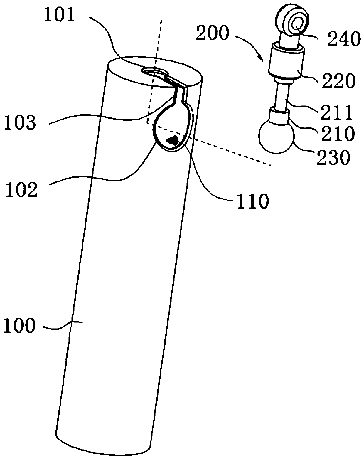
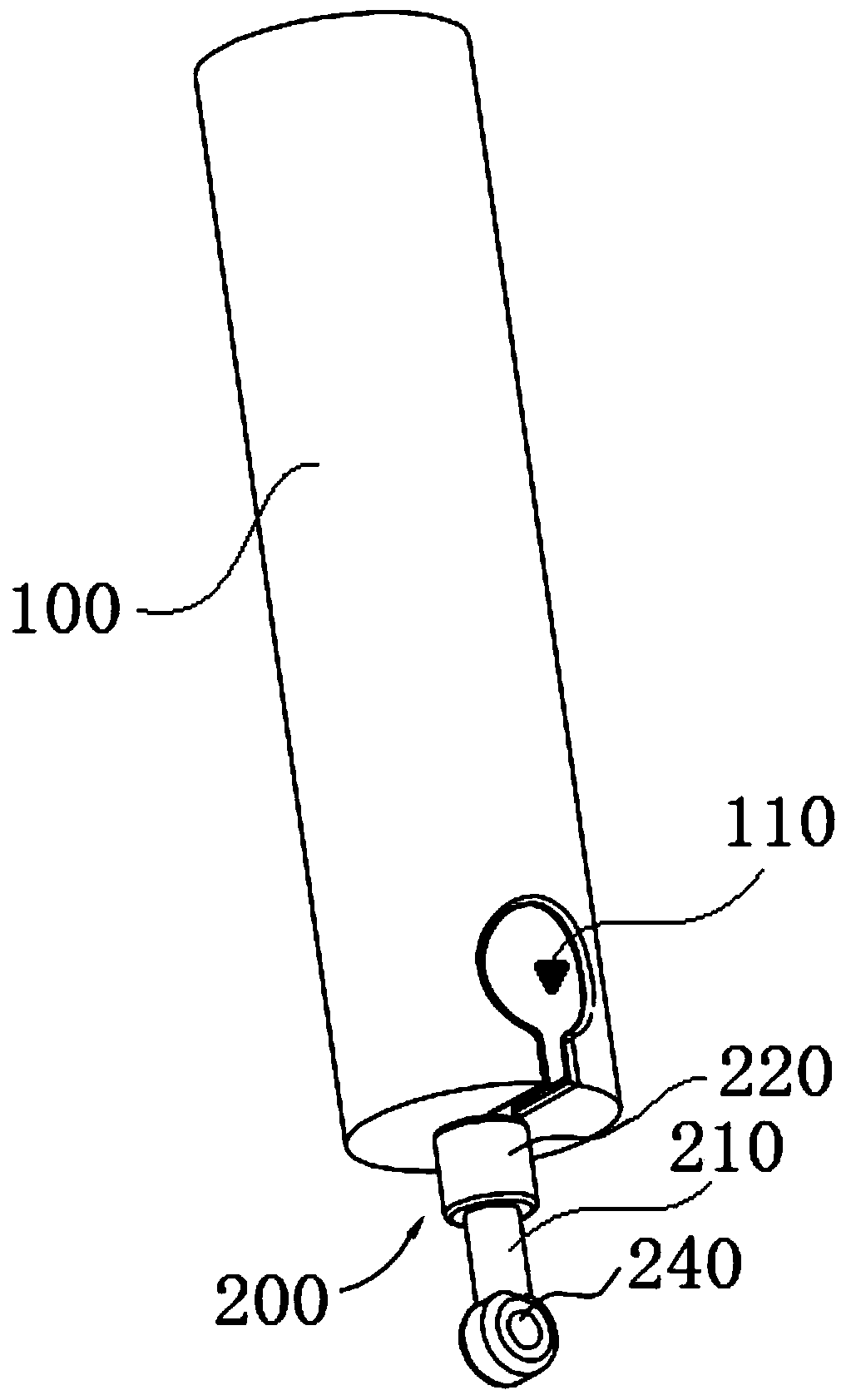
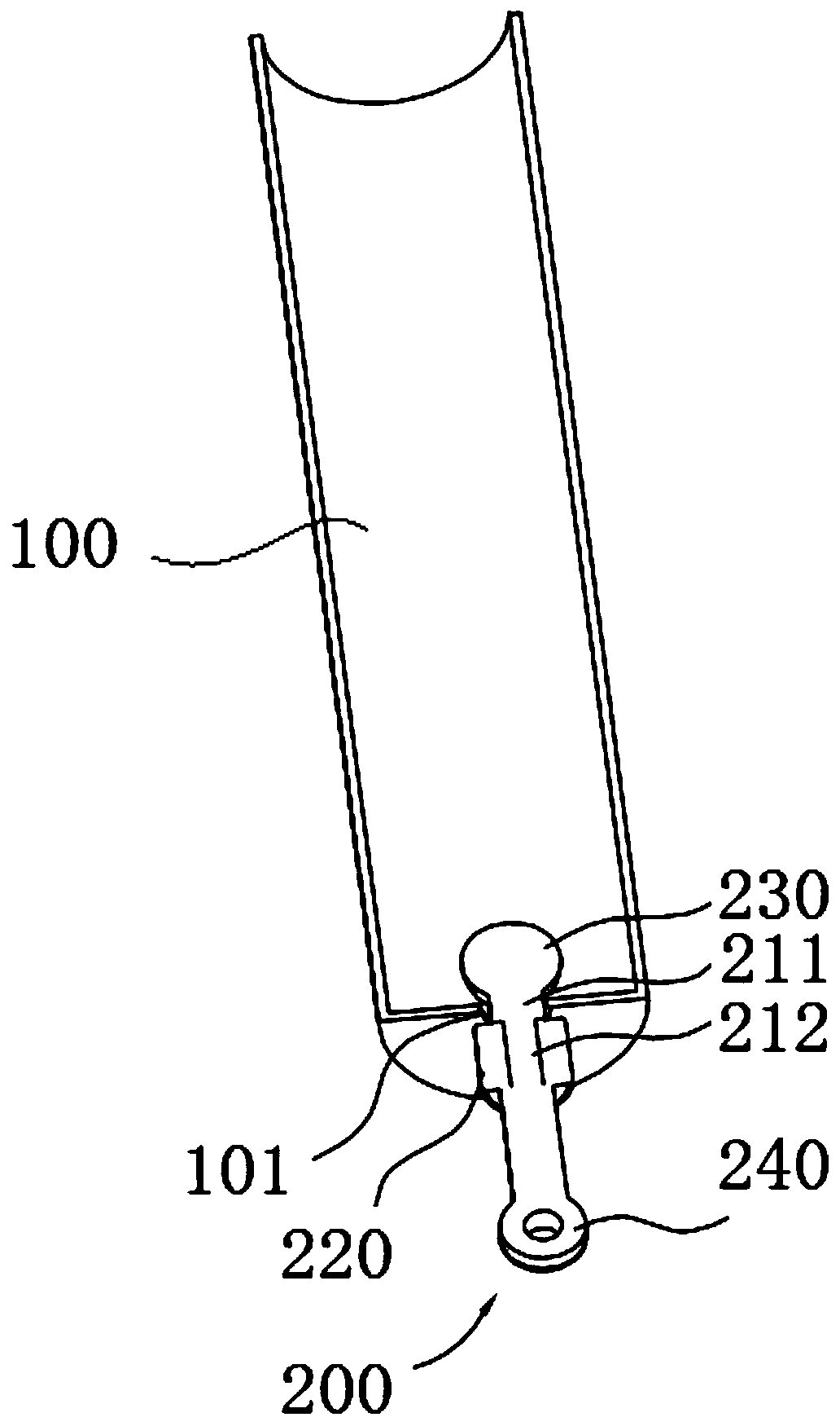
[0032] like Figure 1-3 As shown, the main line swivel structure includes a connecting part 100 and a swivel part 200 , one end of the connecting part 100 is connected to the pole tip (not shown in the figure), and the other end is detachably connected to the swivel part 200 . Specifically, the connecting part 100 can be integrally formed with the rod tip, or can be connected to the end of the rod tip by screw thread or other connection methods.

[0033] A bo...


PUM


Abstract

The invention discloses a main line rotating ring structure used for being connected with a pole tip. The main line rotating ring structure used for being connected with the pole tip comprises a connection part and a rotating ring part which are detachably connected, wherein a first through hole is formed in one bottom of the connection part, a second through hole is formed in the side wall of theconnection part, the first through hole and the second through hole communicate through an open groove, and the first through hole, the second through hole and the open groove form a first notch usedfor enabling the rotating ring part to be connected with the interior of the connection part; the rotating ring part comprises a central rod, a limiting part and a ring, and the limiting part and thering are connected with two ends of the central rod respectively; and after the rotating ring part enters the first through hole through the first notch, the rotating ring part is limited to the interior of the first through hole by a fixing part. The main line rotating ring structure used for being connected with the pole tip is composed of the two parts which can be detached and separated, fastfirm connection and detachment of a main line group and the pole tip can be achieved, and the phenomena of deformation and damage, due to the fact that a hollow line is directly and repeatedly sleeved with the main line group, of part of a main line are avoided at the same time.

Description

technical field [0001] The invention relates to the technical field of fishing gear, in particular to a main line swivel structure used for connecting with a pole tip. Background technique [0002] In the prior art, the rod tip of the fishing rod is generally connected to one end of the rotating ring, and the other end of the rotating ring is connected to the hollow wire. The end of the hollow wire needs to be knotted to facilitate the binding or sleeve of the main line group on it. Connection, so as to realize the connection between the main line group and the pole tip. When the main line group is tied to the hollow wire with a knot to realize the connection between the main line group and the rod tip, there is a defect that it takes time and effort to disassemble the main line group after use; When realizing the connection between the main line group and the rod tip, the main line group has been wound and disassembled for many times, which will cause deformation and damag...

Claims


Application Information

Patent Timeline
Patent Type & Authority Applications(China)
IPC IPC(8): A01K87/00A01K87/02A01K87/04
CPCA01K87/00A01K87/02A01K87/04
Inventor 李志新
Owner 李志新
Features
  • R&D
  • Intellectual Property
  • Life Sciences
  • Materials
  • Tech Scout
  • Unparalleled Data Quality
  • Higher Quality Content
  • 60% Fewer Hallucinations
Learn More