
Transport vehicle material box discharging device

A technology of a discharging device and a transport vehicle, which is applied in the directions of transportation and packaging, transporting objects, and vehicles used for freight transportation, can solve the problems of increasing human labor and labor costs, increasing the difficulty of handling, and limited space, and achieves convenient grasping. The effect of taking, reducing labor and labor costs, and avoiding the drop of goods

Active Publication Date: 2020-06-19
嘉善剑桥机械股份有限公司
View PDF7 Cites 1 Cited by
  • Summary
  • Abstract
  • Description
  • Claims
  • Application Information

AI Technical Summary

Problems solved by technology

[0002] At present, when the goods placed in the transport car material box need to be discharged, most of them are manually entered into the car material box for handling, and it requires the cooperation of multiple people to unload the goods inside the car material box, thus Increased human labor and labor costs, and when the goods located in the innermost part of the car material box are unloaded, a spec

Method used

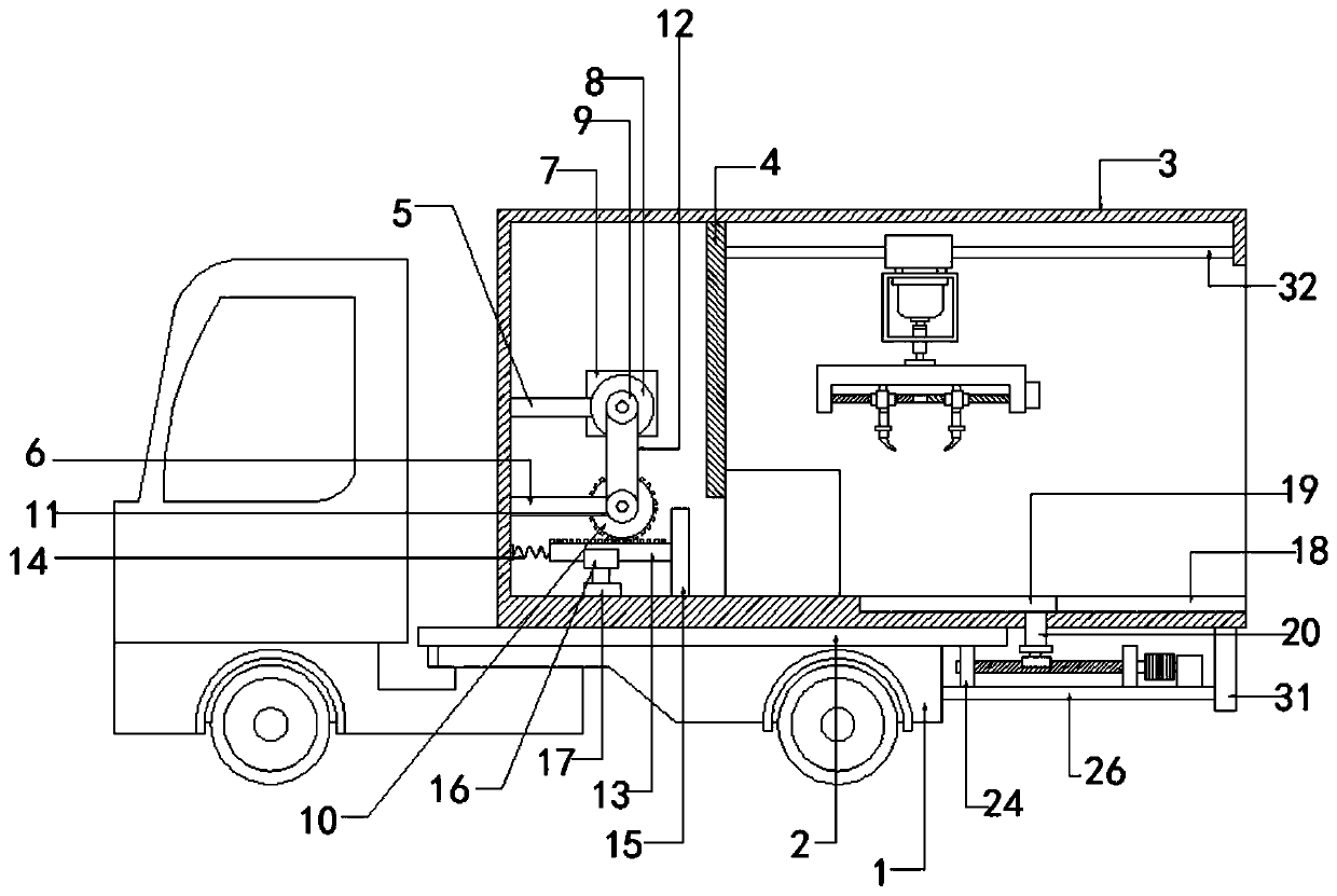

Image

  • Transport vehicle material box discharging device
  • Transport vehicle material box discharging device
  • Transport vehicle material box discharging device

Examples


Embodiment 1

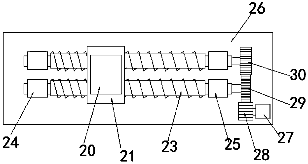
[0027] Embodiment one, such as Figure 1-3 As shown, a transport vehicle material box discharge device according to an embodiment of the present invention includes a vehicle body, a baffle plate 1, a bottom plate 2 and a vehicle material box 3, the bottom of the vehicle material box 3 is fixed with the bottom plate 2, Both sides of the bottom of the base plate 2 are provided with the baffle plate 1, and the baffle plate 1 is fixed on the vehicle body, wherein, the opening of the vehicle material box 3 and away from the vehicle material box 3 A partition 4 is provided on the upper part of one side, and the partition 4 divides the interior of the vehicle material box 3 into a left cavity and a right cavity. The second connecting rod 6 below the connecting rod 5, the first connecting rod 5 and the end corresponding to the partition plate 4 are interspersed with a shaft one, and the input end of the shaft one is connected with a motor two 7, so The other end of the first shaft is...

Embodiment 2

[0028] Embodiment two, such as figure 1 As shown, one end of the support plate 26 is welded to the side end of the baffle plate 1 , the other end of the support plate 26 is provided with a bracket 31 , and the top of the bracket 31 is fixed to the bottom end of the vehicle material box 3 .

Embodiment 3

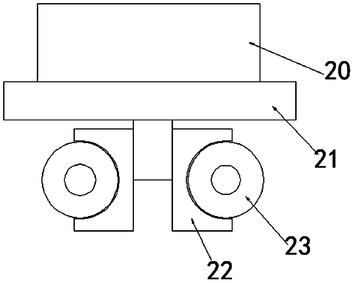
[0029] Embodiment three, such as image 3 As shown, the clamping blocks 22 on both sides and the side that is in contact with the screw 23 are both provided with a half-arc groove, and an internal thread structure 1 that is threadedly matched with the screw 23 is provided in the half-arc groove.


PUM


Abstract

The invention discloses a transport vehicle material box discharging device. The device comprises a vehicle body, baffles, a bottom plate and a vehicle material box, the bottom plate is fixed to the bottom of the vehicle material box, the baffles are arranged on the two sides of the bottom of the bottom plate, And the baffles are fixed on the vehicle body, wherein a partition plate is arranged onthe upper portion of the side, away from an opening of the vehicle material box, in the vehicle material box, the interior of the vehicle material box is divided into a left cavity and a right cavityby the partition plate, a first connecting rod and a second connecting rod positioned below the first connecting rod are arranged at the lower part in the left cavity, a first shaft rod is arranged atthe end, corresponding to the partition plate, of the first connecting rod in a penetrating mode, the input end of the first shaft rod is connected with a second motor, the other end of the first shaft rod is sleeved with a rotating disc, and a main belt wheel is movably connected to the middle of the side, away from the first shaft rod, of the rotating disc. The device has the following advantages: the increased labor force and labor cost of manual carrying are reduced, and the innermost cargos in the vehicle material box can be conveniently discharged.

Description

technical field [0001] The invention relates to the technical field of discharge devices, in particular to a discharge device for a material box of a transport vehicle. Background technique [0002] At present, when the goods placed in the transport car material box need to be discharged, most of them are manually entered into the car material box for handling, and it requires the cooperation of multiple people to unload the goods inside the car material box, thus Increased human labor and labor costs, and when the goods located in the innermost part of the car material box are unloaded, a special carrier needs to enter the innermost part of the car material box to move the goods to the outlet of the car material box. The space inside the material box is limited, which increases the difficulty of handling when the carrier is carrying, and brings great inconvenience to the transportation. Therefore, there is an urgent need for a transport car material box discharging device t...

Claims


Application Information

Patent Timeline
IPC IPC(8): B60P1/00
CPCB60P1/00B60P1/006
Inventor 费永根
Owner 嘉善剑桥机械股份有限公司
Learn More