Dual-channel electrostatic discharge protecting circuit based on RC-triggering

An electrostatic discharge protection, dual-channel technology, used in emergency protection circuit devices, emergency protection circuit devices, circuits, etc. for limiting overcurrent/overvoltage, which can solve the problem of full-chip electrostatic discharge protection design, discharge The degradation of the electrostatic protection ability of the device and the complex physical process of the device can achieve the effect of improving the forward discharge performance, solving the degradation of the electrostatic protection ability, and improving the opening speed.

Inactive Publication Date: 2010-02-03
BEIJING MXTRONICS CORP +1
View PDF0 Cites 20 Cited by
  • Summary
  • Abstract
  • Description
  • Claims
  • Application Information

AI Technical Summary

Problems solved by technology

Currently commonly used trigger circuit structures to increase the gate channel conduction current of NMOS devices include, for example, figure 1 The gate-coupled structure shown and figure 2 The gate drive structure shown, but their gate 55 is directly pulled to the same level as the power supply 1, because the gate 55 is relatively weak, so this may cause gate oxide breakdown, even if there is no breakdown, the gate oxide on the The high voltage will also cause the degradation of the electrostatic protection ability of the discharge device
Therefore, most of the currently commonly used electrostatic protection circuit designs based on NMOS devices use substrate grounding, relying on the reverse avalanche breakdown of the parasitic reverse PN junction between the substrate and the drain, and then trigger the entire parasitic drain, The NPN between the substrate and the source is turned on and discharged, but the physical process of this trigger method is complex, time-consuming, and the turn-on voltage is high, which is increasingly unsuitable for the full-chip electrostatic discharge protection design of large-scale integrated circuits

Method used


Image

  • Dual-channel electrostatic discharge protecting circuit based on RC-triggering
  • Dual-channel electrostatic discharge protecting circuit based on RC-triggering
  • Dual-channel electrostatic discharge protecting circuit based on RC-triggering

Examples


Embodiment Construction

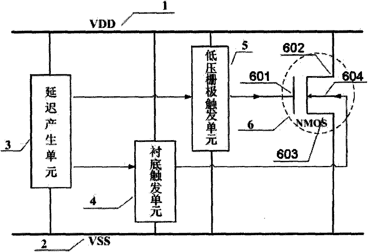
[0022] Below in conjunction with accompanying drawing and specific embodiment the present invention is described in further detail:

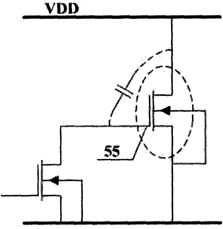
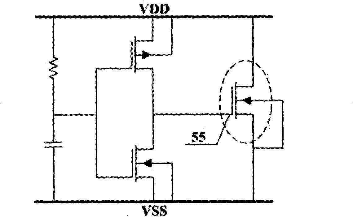
[0023] Such as image 3 As shown, the present invention is composed of a delay generation unit 3, a substrate trigger unit 4, a low-voltage gate trigger unit 5 and an electrostatic discharge device 6, and the electrostatic discharge device adopts an NMOS device. The delay generation unit 3 , the substrate trigger unit 4 , the low-voltage gate trigger unit 5 and the electrostatic discharge device 6 are connected in parallel and connected between the power supply 1 and the ground 2 . Because both the substrate trigger unit 4 and the low-voltage gate trigger unit 5 need to be driven by a certain delay pulse, and the delay time of these two driving pulses corresponds to the discharge time of the ESD process, so the substrate trigger unit 4 and the low-voltage gate trigger unit The unit 5 can use the same time delay, so in the present invention, the...


PUM


Abstract

A dual-channel electrostatic discharge protecting circuit based on RC-triggering is composed of a delay generation unit, a substrate trigger unit, a low-voltage grid trigger unit and an electrostaticdischarger. When positive electrostatic discharge occurs on a power supply, the delay generation unit in the protecting circuit can generate a delay pulse to respectively drive the substrate trigger unit and the low-voltage grid trigger unit, and the combined action of the substrate trigger unit and the low-voltage grid trigger unit reduces the threshold voltage of the electrostatic discharger, improves the opening speed of the electrostatic discharger and enhances the positive discharge performance of the electrostatic discharger; when negative electrostatic discharge occurs on a power line,a parasitic inverse diode between a source electrode in short circuit with the electrostatic discharger and a substrate and a drain electrode is mainly used for electric discharge to realize better negative static voltage protection; and the design circuit in the invention keeps closed in the case of normal power-on of the power supply and normal operation of a chip.

Description

technical field [0001] The invention relates to an integrated circuit electrostatic discharge protection circuit, in particular to an RC-triggered dual-channel electrostatic discharge protection circuit with low trigger voltage, high conduction speed, and high conduction uniformity, which is suitable for full-chip protection Power ground protection design. Background technique [0002] Electro-Static Discharge (ESD) is one of the most important reliability issues in the development of CMOS integrated circuits today. With the rapid development of microelectronics technology, the feature size of semiconductor devices has been greatly reduced, and various advanced processes have been widely used. , causing the harm caused by ESD to become more and more serious. According to statistics, more than 40% of the failures of integrated circuits are caused by ESD, which increases the research and development cycle, increases the cost of product research and development, delays the tim...

Claims


Application Information

Patent Timeline
Patent Type & Authority Applications(China)
IPC IPC(8): H02H9/00H02H9/04H01L21/60
Inventor 李志国岳素格孙永姝
Owner BEIJING MXTRONICS CORP
Why Eureka
Try Eureka