A Method for Measuring the Cathode Proximity Focusing Distance of Super Second Generation Image Intensifier

A technology of focusing distance and image intensifier, which is applied in the direction of measuring device, instrument, optical instrument test, etc., to avoid economic loss and avoid the risk of breakdown

Active Publication Date: 2020-11-27
NORTH NIGHT VISION TECH
View PDF6 Cites 0 Cited by
  • Summary
  • Abstract
  • Description
  • Claims
  • Application Information

AI Technical Summary

Problems solved by technology

[0006] In order to solve the problem of measuring the close-to-close focus distance of the cathode of the image intensifier, the present invention proposes a method for measuring the close-to-close focus distance of the cathode of the super-second-generation image intensifier

Method used


Image

  • A Method for Measuring the Cathode Proximity Focusing Distance of Super Second Generation Image Intensifier
  • A Method for Measuring the Cathode Proximity Focusing Distance of Super Second Generation Image Intensifier

Examples


Embodiment 1

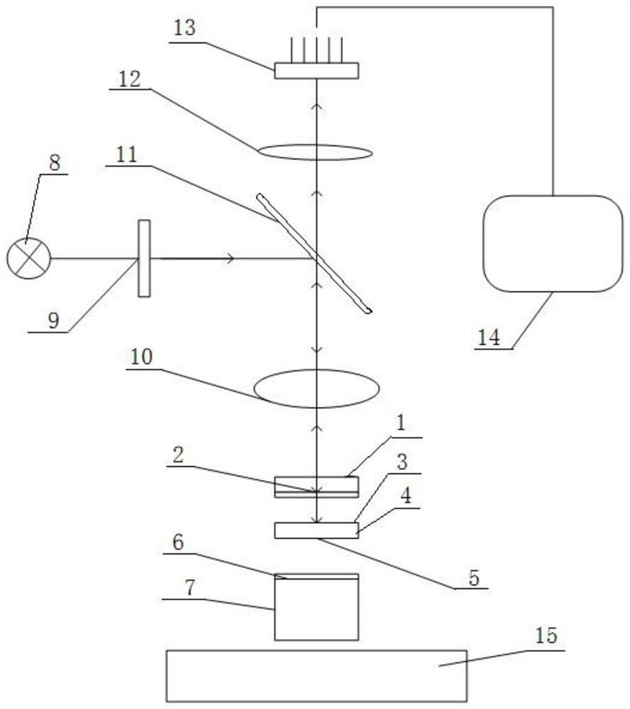
[0029] Use the method of the present invention to measure the close-fitting focus distance of the cathode of the image intensifier, such as figure 2 As shown, the objective lens 10, the half mirror 11, the eyepiece 12, and the CMOS device are fixed sequentially from bottom to top using a frame, and the CCD or CMOS device is connected to the computer 14, and the stage 15 is set to place the image intensifier at the same time. The table 15 can move in the X and Y directions in the plane; and a controller for the fine-tuning mechanism of the objective lens focus can be moved in the Z direction.

[0030] It includes the following steps: (1) Turn on the working power of the tungsten lamp, adjust the working current to the rated value, and let the current stabilize for 5 minutes. The interference filter used in the optical path is a 980nm interference filter.

[0031] (2) Turn on the working power of the CMOS device, turn on the computer 14, and make the CMOS camera work normally....

Embodiment 2

[0036] On the other hand, the present invention can also be used for measuring the distortion of image intensifier microchannel plate 4, comprises the steps:

[0037] (1) Turn on the working power of the tungsten filament lamp, adjust the working current to the rated value, and let the current stabilize for 5 minutes. The interference filter used in the optical path is a 980nm interference filter.

[0038] (2) Turn on the working power of the CMOS device, turn on the computer, and make the CMOS camera work normally. The target size of the CMOS device used is 1 inch, the resolution is 800H×600V, and the frame frequency is 25Hz. Place an image intensifier with an effective cathode diameter of Φ40mm on the stage 15 of the measuring device, with the photocathode facing upwards and facing the objective lens 10, while making the center of the photocathode coincide with the axis of the measuring device. The magnification of the objective lens 10 is 10 times.

[0039] (3) Adjust th...


PUM


Abstract

The invention, which belongs to the technical field of low-light-level image intensifiers, relates to a method for measuring a cathode proximity focus distance of a super-second-generation image intensifier. A near-infrared monochromatic light with a wavelength range of from 900nm to 1000nm, preferably a range of from 950nm to 1000nm is used for measuring a cathode proximity focus distance of an image intensifier. A distance between an objective lens and a cathode casement window is adjusted, the objective lens is arranged at a photocathode film layer, and a focusing position A is measured; the objective lens is focused at an input end of a microchannel plate and a focusing position B is measured; and a difference between the position B and the position A indicates a cathode proximity focus distance of the image intensifier, so that the cathode proximity focus distance deltaz is equal to the difference between the B and the A. With the method provided by the invention, the cathode proximity focus distance of the super-second-generation image intensifier can be measured precisely and effectively and thus an image intensifier on which impact testing can not be carried out is determined, so that the risk of puncturing on the image intensifier is eliminated and thus unnecessary economic losses are avoided.

Description

technical field [0001] The invention belongs to the technical field of low-light image intensifiers, and relates to a method for measuring the cathode proximity focusing distance of a super-second-generation image intensifier. Background technique [0002] The low-light image intensifier (hereinafter referred to as the image intensifier) ​​is the core of the low-light night vision device, and its performance determines the quality of the low-light night vision device. At present, the image intensifier mainly produced in China is the super-second generation image intensifier, and its structure is as follows: figure 1 As shown, it is mainly composed of a cathode glass window 1, a photocathode 2, a microchannel plate 4, a fluorescent screen 6 and an optical fiber output window 7. The photocathode 2 plays the role of weak light imaging, the microchannel plate 4 plays the role of electron amplification, and the fluorescent screen 6 plays the role of image display. When the weak...

Claims


Application Information

Patent Timeline
Patent Type & Authority Patents(China)
IPC IPC(8): G01M11/04
CPCG01M11/00
Inventor 李晓峰曾进能李廷涛杨振汤文梅
Owner NORTH NIGHT VISION TECH
Why Eureka
Try Eureka