Mould provided with suspension type core-pulling rod screen placing structure

A mesh structure, suspension technology, applied to household appliances, other household appliances, household components, etc., can solve the problems of reducing the mold opening stroke, the filter screen is crushed, the filter screen is squashed and shiny, etc., and the mold opening stroke can be reduced. Effect

Pending Publication Date: 2020-06-23
蚌埠市兰天模具科技股份有限公司
View PDF0 Cites 0 Cited by
  • Summary
  • Abstract
  • Description
  • Claims
  • Application Information

AI Technical Summary

Problems solved by technology

The height of the mold is reduced, so that the mold clamping can be completed without an excessively high slider, and the slider is not easy to tilt during the mold clamping process, which causes the non-woven fabric of the filter element to be flattened, shiny or even crushed, which solves the problem in the prior art The length of the filter screen is too long, which leads to the high mold slider. When the mold is closed, the slider is locked and easily tilted slightly, causing the filter screen to be flattened and shiny, or even the filter screen to be crushed, thereby reducing the yield of plastic products. (2) After the injection molding is completed, the fixed template is opened, and the nozzle spring in the mounting hole on the fixed mold insert pushes the injection nozzle downward, and the nozzle is separated from the plastic sleeve, and the spring pushes the mandrel out of the movable mold part, the mandrel and the plastic product. It is separated from the upper mold cavity on the fixed mold insert and the lower mold cavity on the movable mold insert. Through the above structure and the reduction of the height of the slider, the excessively long mold opening stroke of the mold is reduced, making the mold more stable. Small, suitable for the use of small-sized injection molding machine tools, and solve the technical problem that the overall length of plastic products in the prior art will make the mold opening stroke longer, so there is no need for large-sized injection molding machine tools for injection molding, which increases the cost of injection molding; (3) through There are two installation holes on the fixed mold insert, and a nozzle spring is arranged in the installation hole. The top of the nozzle spring is fixedly connected to the lower surface of the fixed mold seat plate, the nozzle spring is flush with the bottom of the fixed mold insert, and the movable template Before closing the mold with the fixed template, the piston rod of the oil cylinder pushes the slider, and then the mandrel returns between the fixed mold insert and the movable mold insert, and the filter element non-woven fabric is installed on the mandrel, and the fixed template and the movable template are closed. After finishing the mold closing, the setting of the spring under the mandrel assembly makes the mold opening distance between the fixed mold insert and the movable mold insert large when installing the filter element non-woven fabric on the mandrel, making the filter element non-woven fabric easier to install and solving the problem. In the prior art, the mandrel is in the middle of the two sliders, and the normal distance drawn by the sliders seriously hinders the manual installation of the filter element non-woven fabric. The gap is too small, and it is difficult to put the hand in, resulting in low efficiency of filter element non-woven fabric installation, which affects Technical issues of production efficiency

Method used


Image

  • Mould provided with suspension type core-pulling rod screen placing structure
  • Mould provided with suspension type core-pulling rod screen placing structure
  • Mould provided with suspension type core-pulling rod screen placing structure

Examples


Embodiment Construction

[0043] The following will clearly and completely describe the technical solutions in the embodiments of the present invention with reference to the accompanying drawings in the embodiments of the present invention. Obviously, the described embodiments are only some, not all, embodiments of the present invention. Based on the embodiments of the present invention, all other embodiments obtained by persons of ordinary skill in the art without creative efforts fall within the protection scope of the present invention.

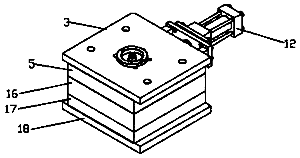
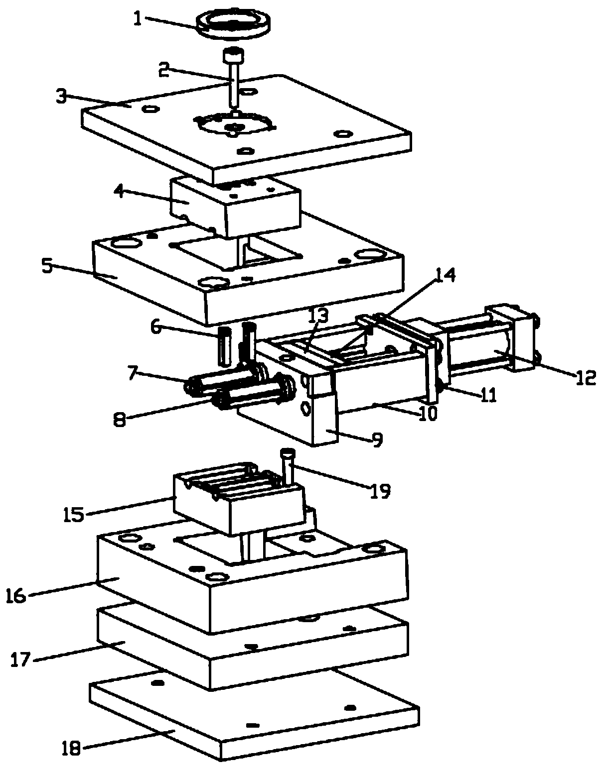
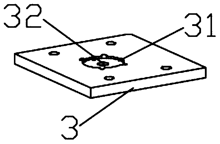
[0044] see Figure 1-14 As shown, the present invention is a mold with a suspended core rod netting structure, including a fixed template 5 and a movable template 16, the fixed template 5 is provided with a fixed mold insert groove 51, and the fixed mold insert groove 51 is provided with There is a fixed mold insert 4, the bottom of the fixed template 5 is provided with an upper groove 54, one side of the fixed template 5 is provided with a rod groove 53, and one s...


PUM


Abstract

The invention discloses a mould provided with a suspension type core-pulling rod screen placing structure. The mould comprises a fixed moulding board and a movable moulding board, wherein a fixed mould insert slot is formed in the fixed moulding board; a fixed mould insert is arranged in the fixed mould insert slot; an upper groove is formed in the bottom of the fixed moulding board; a rod slot isformed in one side of the fixed moulding board; and two upper plate slots are formed in positions, close to the two ends, of one side of the fixed moulding board. According to the mould disclosed bythe invention, a mould opening direction of the mould is perpendicular to the axis of the circle center of a plastic product, and the plastic product is horizontally placed, so that height of the whole mould is greatly reduced. Height of the mould is reduced, so that mould locking can be accomplished without a too high slide block, and a condition that filter element non-woven fabric is flattened,shined and even damaged by pressing is caused as the slide block is not liable to tilt in a mould locking process, and therefore, the technical problem that a yield of the plastic product is reducedas the slide block of the mould is too high due to great length of the filter screen in the prior art, and a phenomenon that the filter screen is flattened, shined and even damaged by pressing is caused as the slide block is locked and is liable to slightly tilt during mould closing is solved.

Description

technical field [0001] The invention relates to the technical field of mold production, in particular to a mold with a suspended core rod netting structure. Background technique [0002] One of the existing molds is to produce cylindrical net-shaped plastic parts, with a layer of filter screen attached to the inner wall. The plastic products produced by the mold belong to the elongated plastic parts with round net shape and filter nets, which are used for automotive filters. Core pieces. [0003] The conventional mold structure is to place the plastic parts vertically (the axis line of the product cylinder is consistent with the mold opening direction), which has many disadvantages: 1. Because the length of the plastic product is long, the mold slider is too high, and the slider is too high when the mold is closed. If the lock is not tight, it is easy to tilt slightly, causing the filter to be flattened and shiny, or even the filter is crushed. If the slider is not locked t...

Claims


Application Information

Patent Timeline
Patent Type & Authority Applications(China)
IPC IPC(8): B29C45/14B29C45/33B29L31/14
CPCB29C45/14065B29C45/33B29C45/332B29L2031/14
Inventor 兰馨朱少礼朱国友
Owner 蚌埠市兰天模具科技股份有限公司
Why Eureka
Try Eureka